Plane - Bisect Points - Circle
Introduction
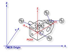
In this exercise, we will create a part coordinate system utilizing a plane for the
orient and origin, two 2D points from which we will obtain a constructed 2D point through
the bisect command then followed by a circle for alignment and origin. The following
example assumes the part is placed on your CMM where the cylinder of the
GeoWidget is
pointing in the -X direction.
 |
 |
|
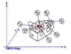
figure 1, Datum target layout |
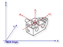
figure 2, Complete PCS |
Practice Steps
Step 1
Request a -Z plane
<b>, if auto-direction is not
activated, you will be asked for the probing direction which you should select as -Z. You
will then be prompted to "Measure -Z Plane", (if auto-direction is active
"Measure Auto-Dir Plane"). Capture points A-1, A-2, A-3 and A-4 as shown in
figure 1.
Step 2
Select Orient
<j>. The orient command will create the
primary datum on the axis that is most normal to the machine coordinate system. In your
PCS Setup Guide, the Z Axis will be signed off.
Step 3
Select Origin
<l>. This will establish the Z origin
which is determined by the normal direction of the -Z plane.
Step 4
|
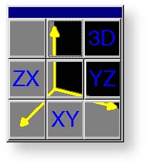 |
| figure 3, Base plane selection |
Select a 2D XY Point
<5 + 2>. The selection of
a 2D point requires two commands. The first command is activated by pressing the
< 5
> key, which will display the 2D and 3D point selection tool, select the PCS base plane
you would like to point to be projected into, see figure 3.
After the selection has been completed, Geomet will prompt you to "Measure XY
Point". Capture points B-1 and C-1.
Step 5
Select the Bisect command <a>. This command will take the two projected XY points
and solve for the bisect point between them. The result will be a 2D XY point.
Step 6
Select Circle
<z>, if auto-direction is not activated,
you will be prompted for the Circle type: ID, OD, IR, or OR, choose ID.
Capture the four data points identified as D-ID/4, see figure 1
Step 7
Select Align
<k>. This will take the just measured
circle center and the previous 2D point created by the bisect routine and perform an
alignment. Your ICS will update to include the secondary datum.
Step 8
Select Origin
<l>. the Circle, which is 2D, provide two
directions when establishing an origin. In our example, the circle can be used for the X
and/or the Y direction. The origin command will prompt you whether to use the X and then
the Y. For our example you should answer <Yes> to both requests. Upon completion,
you will have established PCS 1, see figure 2.
Final Inspection Report
In this exercise, we used a constructed feature, an XY point, as part of the alignment
solution. It is important that you choose the correct features to be used for alignment
based on the completeness of the ICS. The XY points for B-1 and C-1 were chosen as the ICS
lacked an alignment. If two 1D points were chosen, then there would exist an error caused
by the part skewed to the MCS base axis. see
Measurement Features→1D Points
 |
|
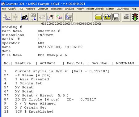
figure 4, Final Inspection Report |
This does not preclude conditions where 1D points could have been used. For example, if
we were working in the PCS that was created in exercise 1, then we would have the correct
probe compensation vector and we could select -X and +X 1D points for B-1 and C-1
respectively, see figure 5. The resulting bisect would create a 1D point on the
centerline of the slot.
|
 |
|
figure 5, 1D Point Bisects |
However, a 1D point followed by a circle can not be combined to form an alignment.
Geomet does not accept this as it causes potential repeatability problems when the slot is
not aligned with the current PCS. Therefore you could repeat the bisect of two additional
1D points captured on the width of the part at the other end from the slot points C and D,
see figure 5. The resulting 1D point derived from the bisect combined with the
previous recalled constructed point could produce the alignment. see figure 5, points
C and D, 1D Point bisects
Related Procedures:
Download PCS Example #6 (.zip)
Go to PCS Examples:
prev
1
2
3
4
5 6
7
8
9
10
11
12
next
Orient,
Align,
Origin,
Plane,
Circle,
2D Point
|


