Command Activation
| b |
Measure→Plane |
 |
| Keyboard |
Main Menu |
Toolbar |
Definition
Planes have locations, attitudes and directions. The location of a plane is defined as
the point at which it is pierced by a PCS axis. The attitude of a plane is defined by the
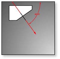
projection angle AX/Y, AY/Z and AZ/X of the plane normal in each of the three PCS base
planes, with range values from 0° to ± 180°.
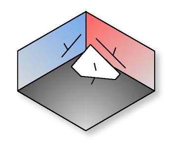 |
| figure 1, Plane
represented in the working PCS |
The direction of a plane is defined by the vector normal, pointing out of the
plane. Figure 1 shows a plane with its projection into each PCS base plane. The normal,
when projected into each PCS base plane provides the attitude in angles, see figures
2, 3, 4.
 |
 |
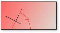 |
figure 2,
AX/Y Projection |
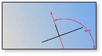
figure 3,
AY/Z Projection |
figure 4,
AZ/X Projection |
The Plane feature may be used to measure non-skewed planes. The printed pierce
point of a measured plane is determined by the PCS axis that is most parallel to the
normal of the measured plane. In the example in figure 1, the pierce point would be report
as a Z axis point. Planes which are essentially parallel to PCS base planes have only two
attitude angles which are meaningful, the third is printed in lower case, as for example
"ax/y" to indicate its reduced significance.
 |
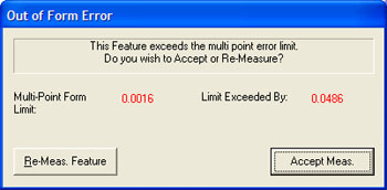 |
figure 5,
Direction Selector |
figure 6,
Out-of-Form Warning |
To measure Planes press the Plane key < b >for a 4 point (or the default number of hits as
established in System Options) plane, or < shift + B > for a multi-point
plane.
 |
|
figure 7, Enter Data Point Count |
If you required additional data points even during point capture, you can
repeatedly press the Plane key which increments the required number by one. If
Auto-Direction is not enabled, you will be
prompted to enter the probing direction, see figure 5. Upon completion of
gathering your data points, Geomet will test the form error to the newly calculated plane.
If the form error exceeds the default setting, see figure 6, you will be prompted
to < Accept > or < Re-Measure > the plane.
The definition of the Boundary Plane is a plane the passes through the minimum or
maximum extreme data point of a measured or constructed plane and parallel to that
reported plane. This plane can be used in all cases which a measured or constructed plane
is be used such as PCS components, constructions and tolerance.
 |
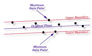 |
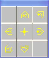
figure 8,
Boundary
Menu |
figure 9,
Example
of Boundary Plane |
Geomet offers two directions from which you can choose from, Upper and Lower. The Upper
Boundary Plane represents the plane constructed at the most positive side of the reported
pierce point. For example a plane reported at Z: +1.345 might have an Upper Boundary Plane
reported at +1.349.
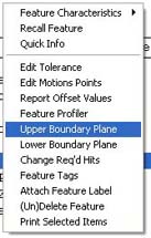
To use the feature, measure or construct a plane, select the plane directly on the
report by left-clicking our mouse over the feature to highlight it . Activate the feature
menu by right-clicking and a menu similar to the one shown in figure 7 will pop-up. Choose
Upper or Lower Boundary Plane and the feature will recalculate showing the new reported
values.
It is suggested to recall the plane, then apply the Boundary plane change to the
recalled plane. This ensures the original plane is available for other construction or
tolerance requirements.
If you do not have the Upper/Lower menu selections in your pop-up, the plane you have
selected is referenced by another operation. You can only change the reported values on
planes that have no reference. However you can recall the plane and then apply Upper/Lower
Boundary Plane.
One example in which this feature can be used is to determine the width of a slot,
see
figure 10. Where the effective distance is the closest two points as if a gage block
were used to identify the width of a slot. Select the plane representing one side of the
slot and report it as an upper boundary plane, then select the opposite plane and report
it as the lower. Obtain the distance <s> between the planes and that distance will
represent the closest points in the slot.
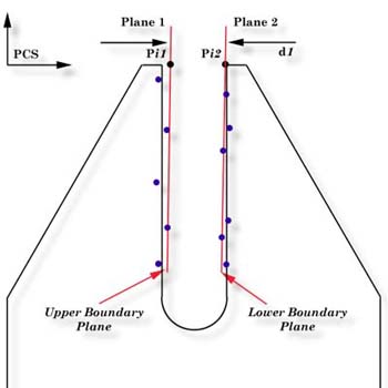 |
| figure 10,
Boundary Plane Slot Example |
It is important that your PCS be established close to the desired location where the
distance should be taken. As shown in figure 10, should the PCS be outside the effective
location the distance is expected, the reported result will not represent the actual
distance.
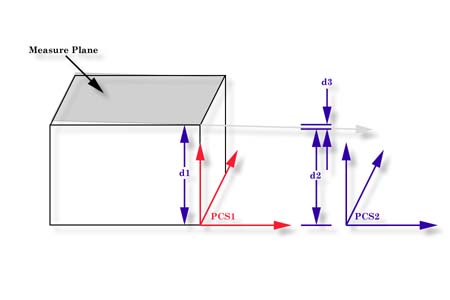 |
| figure 11, Localization of the PCS |
Referring to figure 11, we have two established Part Coordinate Systems. PCS 1 is
established on the base of the 2.000" gage block. PCS 2 is located 4.000" inches
in the X direction from the right side of the gage block.
Two planes were measured, one representing the lower base and one on top of the gage
block, The lower base plane was used to establish the XY PCS Base Plane for both PCS 1 and
2. The top plane had a AZ/X of 89.9943° and the AY/Z was 90.0000°. The intersection with
the pierce point with the PCS1 Z Axis, d1, is reported at 1.9999".
The reported pierce point on the Z axis of PCS2, d2 is 1.9995". By
not having PCS localized to the actual measured surfaces we introduced 0.0004",
d3,
error!
Click here for a more detailed
discussion on Projection Errors.
Tolerance
Tolerance of Planes is available in Cartesian / Linear
format.
|


