Applies to: All Levels of Geomet
Last updated:
Sunday January 09, 2011.
Projection Errors are often overlooked but their effect on the inspection
process are tremendous.
A Coordinate Measuring Machine is a wonderful inspection tool when used by
an experienced operator who has a sound knowledge of inspection processes,
but when used by an operator who has limited knowledge in the inspection process, disastrous results can be delivered that undermine the confidence in the
Quality Department. The ideal CMM operator is one who has in-depth
knowledge in the inspection process as a result of years of manual
inspection techniques.
However, we live in a world that has a shrinking pool of experienced
inspectors as we rely on technology to deliver results. An experienced operator would have the "eye" to identify poor inspection
techniques that result in errors such as Projection Errors.
The Measurement Process
To illustrate, let's use a rather simple test utilizing a
2" Gage Block
and a Micrometer. This is a simple point-to-point measurement and we should
be able produce the correct result with a properly calibrated micrometer
repeatedly.
Using a CMM to perform this same measurement now involves several
components that introduce uncertainty to the final results. Probe
repeatability, CMM structural integrity, scale compensation, software
algorithms, a Coordinate System and the operator are just some of the influences
working against you to obtain the most accurate reading possible. Please see
Tech Note #2 for explanations on some of
these items.
The micrometer provides a direct feedback from the anvils to the
threaded, calibrated thimble. The main influence affecting the
reading is the pressure applied to the anvils and work piece placement. Too much pressure, and the
reading will be small. Not enough pressure or the work piece is held
poorly, you report a larger reading.
The CMM isn't to simple. The touch probe makes contact with a part which
informs the CMM software to capture an XYZ point. The relationship between
the center of the probe and the actual scale is mechanically connected
through a series of components starting with the stylus ball and ending with
a scale reader head. The list below is a typical link from the XYZ measured
point to the Y-Axis Scale:
- Stylus Ball Radius
- Stylus shaft length
- Touch Probe
- Probe Head
- Z-Axis Probe Bar
- X-Axis Bridge Structure
- Y-Axis Main Support Base
- Y-Axis Scale
If the CMM has a cube size of X=40" / Y=80" / Z=25" the distance between
the data point and its reporting Y-Axis scale may have to travel through 70"
or more of superstructure with each component adding its error to the
result!
Example #1 - Measuring our Gage Block
The CMM through its software, allows you to establish
coordinate systems that is not required to be in-line with the natural
movement of the CMM axes. This coordinate system may even need to be outside the measuring cube
as in the case of car coordinates in automotive inspections. The usage and
placement of coordinate systems is one key component, that when used
properly, will deliver the results you expect.
It is important to establish a Part Coordinate System (PCS) close to the desired location where the
distance should be reported. As shown in the figure below, should the PCS be outside the effective
location the distance is expected, the reported result will not represent the actual
distance.
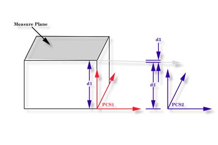 |
| figure 11, Localization of the PCS |
Referring to figure above, we have two established Part Coordinate Systems. PCS 1 is
established on the base of the 2.000" gage block. PCS 2 is located 4.000" inches
in the X direction from the right side of the gage block.
Two planes were measured, one representing the lower base and one on top of the gage
block, The lower base plane was used to establish the XY PCS Base Plane for both PCS 1 and
2 which ensures that Z= 0.000 is common to both PCSs. The top plane has a AZ/X of 89.9943° and the AY/Z was 90.0000°. The intersection with
the pierce point with the PCS1 Z Axis, d1, is reported at 1.9999".
The reported pierce point on the Z axis of PCS2, d2 is 1.9995". By
not having PCS localized to the actual measured surfaces we introduced 0.0004",
d3,
error!
Example #2 - Aligned Cylinder on Flange
 In
this example we have a 0.25" diameter cylinder that passes through the outer wall of
a larger cylinder. The center axis of the cylinder coincides with the axis of the
larger cylinder.
In
this example we have a 0.25" diameter cylinder that passes through the outer wall of
a larger cylinder. The center axis of the cylinder coincides with the axis of the
larger cylinder.
The reporting coordinate system is the center of the cylinder identified
as PC1. The cylinder has an
inside diameter of 3.875" and a wall thickness of 0.25".
Once the PCS has been established on the ID of the larger cylinder, the
stylus is articulated to allow entrance into the 0.25" through cylinder. Six
data points are captured and the cylinder is calculated.
Problem: The cylinder is reported as:
| Characteristic |
Actual |
| Diameter |
0.2505" |
| X |
0.0012" |
| Z |
0.0001" |
| AX/Y |
89.9828° |
| AY/Z |
0.000° |
The through cylinder is expected to be ±0.0002" in the X-Axis with a
nominal of 0.0000". Clearly the reported value exceeds the allowable
positioning.
Analysis: Looking at the reported projection angles we
show a AX/Y of 89.9828° or 0.0172° which we can calculate the X-Axis
deviation with. Projecting this over a distance of 4.000" we have a error of
0.0012"! This coincides with the reported X-Axis position. Adding to
the projection error is the length of the
measured cylinder which is less than the thickness of the cylinder wall.
Solution: Isolate projection error by
translating PCS1 in the Y-Axis by 4.000"
which creates a new PCS2. This will place the new PCS in the
middle of the cylinder wall. Now measure the through cylinder which will
report its position by piercing the ZX base plane of PCS2.
Press the <l>, Origin command
and establish a new PCS with the ZX reported position from the just measured
cylinder. Now we need to recast this position into the original PCS for
reporting. This can be accomplished by recalling the original PCS, <'>
Recall PCS command. Finally recall
the Origin created with the previous step as a 3D Point into the current
PCS. This is done with the, <shift + H> Recall Comps, command.
This recalled 3D Point will report a X= 0.000" eliminating the projection
error!
Measured Feature Selection
Using a multi-point feature may not always deliver the expected results.
In the case of a simple point-to-point gage block measurement, we could have
used a -Z measured Point. With each -Z Point taken on top of the gage block,
there will be no projection error. However, the full affect of CMM errors
will be applied. In a multi-point feature, such as a plane, a single data
point that has a repeatable error would be reduced by the remainder of data
points in the calculation.
If a single point feature was being used and a repeatable error is
introduced, the full error is used in the reporting. It is not uncommon to
repeat a reading and have a spread of 0.00014" over many readings.
To test your CMM, fix a artifact on your table in the +X position of the
measuring cube and clamp it down to prevent movement. Align your stylus in
front of the artifact and lock the X and Z axes. Set the software up to
capture +Y points and begin to make contact with the artifact. Move the CMM
to different back off distances and approach speeds, but contact the
artifact is normal touch probe speeds. Repeat this test by clamping the
artifact at the furthest -X direction and compare the results.


