Helmel Engineering Products, Inc. Customer Support -- Tech Note #2
Multi-Point Feature and CMM Inherent Errors:
Applies to: All Levels of Geomet, Geomet 501
Last updated:
Tuesday December 08, 2009.
NOTICE
Information contained within this document is subject to change without notice. No part
of this document may be reproduced or transmitted in any form or by any means, electronic
or mechanical, for any purpose without written authorization from Helmel Engineering
Products, Inc.
This document contains proprietary subject matter of Helmel Engineering Products, Inc.
and its receipt or possession does not convey any rights to reproduce disclose its content
or to manufacture, use or sell anything it may describe. Reproduction, disclosure or use
without specific written authorization of Helmel Engineering Products, Inc. is strictly
forbidden.
© Helmel Engineering Products, Inc. 1985 - 2006. All right reserved.
GEOMET®, MICROSTAR® are trademarks of
Helmel Engineering Products, Inc.
Introduction
Technical Note #2 - Multi-Point Feature Inherent Errors
Published October, 14, 2003
Edward R. Yaris - Software Development Manager, Helmel Engineering Products, Inc.
Commonly found Errors
- CMM Calibration Errors
- Probing Errors
- Operator Influences
- Data Point Spread
System Errors
In all multi-point features, the ability to report accurate and repeatable
results are subject to the quality of the gathered data points. Influencing
your measured results will be the stacking of inaccuracies within your
measuring system generated by the commonly found errors listed above.
Coordinate Measuring Machine
Scale Error
The CMM has inherent inaccuracies such as axial linear error and mechanical
limitations on squareness, parallelism and perpendicularity. Every CMM has a
scale attached to each axis of movement. This scale can be a mechanical /
optical or laser configuration. In the case of a mechanical / optical there
exists positioning error which CMM manufacturers will attempt to compensate
for through hardware or software.
For example when a scale is installed, it will be compared to a master
scale or laser. The CMM will be positioned along the scale at different
points and the reported position will be compared to the master. If the
position reported by the laser was 10.00000 and the CMM reported 9.99875 The
difference will be the linear inaccuracies of the scale at that position. In
a single linear compensation, a scale factor will be applied to the CMM’s
position feedback to correct for the error. However, this method of
compensation works with the overall average and does not correct for local
inaccuracies along the scale.
The chart below demonstrates the Position Error measured compared to a Master Scale or
Laser. The scale along the left side illustrates the deviation error.
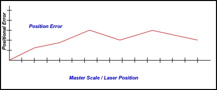 |
| figure 1, Original Positional Error |
After single line compensation has been applied the deviation error has been minimized
to create a more accurate position.
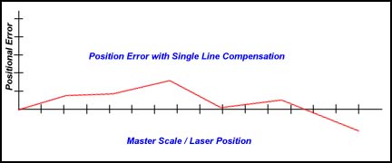 |
| figure 2, Single Linear Compensation Applied |
One limitation in single line compensation is that the variances along the
scale can not be individually removed. Therefore the single line
compensation method only averages out the entire scale without regard to
multiple position errors. When the CMM is positioned along the scale, some
error characteristic will still be built in.
Non-Linear Scale Compensation
Another method to minimize scale-positioning error is the Non-Linear
method. This method builds a table of compensation values that can be
measured and created along the various undulations along the scale. It
requires that the CMM has a reproducible home position for all axes. The
chart below illustrates a non-Linear method applied to the same scale shown
above. The error has been reduced further.
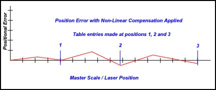 |
| figure 3, Non-Linear Compensation Applied |
As with any linear compensation method, if the scale is not mapped out over
every position, then an error will always be present influencing your
results.
Mechanical Intrinsic Accuracy
The next error that a CMM can have is called intrinsic accuracy, the
mechanical accuracy of the CMM. These include Squareness, Perpendicularity
and Parallelism of the structure of your CMM. If the X-axis is not
perpendicular to the Y-axis, then when the probe is moved along the X-axis a
deviation in Y will occur. To test for this, place a certified square down
on the CMM base. Place a .0001” or better indicator on the probe bar and
lock the Z and X-axes from moving. Move the CMM in the Y-axis with the
Indicator in contact with the square. Set the square edge parallel with the
Y-axis travel until no movement is shown on the indicator. Unlock the X-axis
and reposition the indicator so it contacts the square and lock the Y-axis.
Move the indicator along the X-axis and you should not see movement on the
indicator dial.
Repeat this procedure in the front and back location on your CMM to
ensure the X to Y-axis relationship is perpendicular thoughout the measuring
envelope. An additional test would be to raise the square to the highest
point within your measuring cube and repeat the procedure.
Should you see a deviation, then your CMM is not square in the XY
plane. Any measurements taken will have an inherent inaccuracy.
The Z-axis should be perpendicular to the CMM base. To test this, place a
.0001” or better indicator on the probe bar. Place a certified square on the
CMM base with the surface parallel to the Y-axis. Lock your X and Y-axis
with the indicator in contact with the square. Move your Z-axis up and down,
you should not see any movement on the indicator. Now repeat the test with
the surface of the square parallel to the X-axis.
Should you see a deviation, then your CMM is not square in the ZX
and / or YZ plane. Any measurements taken will have an inherent inaccuracy.
BallBar Test for CMMs
One method to accurately evaluate axis to axis relationships is found in the
B89.4.1,
Methods for Performance Evaluation of Coordinate Measuring Machines published by
ASME International. This Standard
establishes requirements and methods for specifying and testing the performance of
coordinate measuring machines (CMMs) having three linear axes perpendicular to each other
and up to one rotary axis positioned arbitrarily with respect to these linear axes. In
addition to clarifying the performance evaluation of CMMs, this Standard seeks to
facilitate performance comparisons among machines by unifying terminology, general machine
classification, and the treatment of environmental effects.
The Ball Bar consists of a temperature stabilized bar with two high precision spheres
mounted at each end, see figures 4 and 5. The length between the spheres is not
necessary to be known. The Ball Bar is positioned within the measuring area of the CMM in
28 different positions as described in ASME B89.4.1.
 |
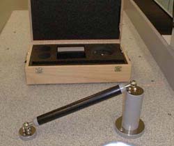 |
| figure 4, Ball Bar Set |
figure 5, Evaluated Ball Bar Position |
The process of gathering data involves the measuring of each sphere and
calculating the direct line distance between them. One advantage of this
method over other methods, such as a step gage, is the averaging effect of
the probe lobe errors. In any given direction around the traditional touch
probe, there exists a lobing error that can be measured, but not effectively
removed from a feature calculation. By capturing data points evenly around
the sphere, the lobe error variations are not removed, but averaged out to
obtain a closer size and location reporting of the actual sphere.
Once all 28 positions have been calculated, they can be entered in a Excel spreadsheet,
download. The average of all 28 positions is
first obtained and a companion column of actual - average is calculated. These values are
then plotted as shown in figure 6.
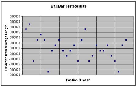 |
| figure 6, Plotted Ball Bar Test Results |
The Maximum and Minimum values are found from the deviation column. The
spread between these values is considered the working tolerance. This value
is often reported as the volumetric accuracy of a CMM. It should be noted
that the length of the ball bar is often a small fraction of the actual
measuring area. Therefore, the reported working tolerance only reflects the
area the cubic size of one ball bar length in the X, Y, and Z and should not
be used to define the entire CMM.
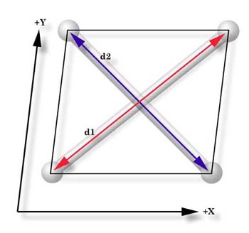 |
| figure 7, X / Y squareness |
In figure 7, we can visualize how to interpret the Ball Bar tests. We can see the
direct effect of a squareness deviation of the X versus Y axis. The distances of the
measured lengths, d1 and d2, should be equal when the
CMM has been properly setup. As the illustration shows, d1 being greater
than d2 demonstrates that the relationship between the X and Y axis are
not perpendicular. When properly interpreted by a trained calibration engineer, all 28
positions will effectively provide a picture of the intrinsic characteristics of your CMM.
Many CMM manufacturers have abandoned building intrinsic accuracy in
favor of 3D software compensation. This allows building of a CMM with little
attention to the accuracy of the assembly. The accuracy is acomplished by
mapping the CMM with a known standard, such as a laser, then providing 3D
compensation algorithms to correct the inherent errors. However using only a
laser does not remove all the inherent inaccuracies within the entire
measuring cube.
There is no correct answer as to which method delivers a more accurate
CMM. In both cases, the ability to perform field calibrations often becomes
an economic cost the user must absorb. To perform a field calibration by
mapping the CMM with a laser system is a higher cost than adjusting for
intrinsic accuracy.
Probing System Errors
Every probe system introduces inaccuracies to your data point gathering.
These include capture speed, lobe errors, stylus lengths and probe contact
pressure. Understanding the errors within the probe system can be very
difficult. Most electronic touch probes have no index position when
installed on a CMM and can rotate to a new location moving the lobe error.
Additionally, electronic touch probes are a simple switch and can not
determine the approach vector at the point of contact. This simple fact
makes it very difficult to map out probe errors.
 |
| figure 8, Lobing Error |
Lobe errors are mechanical limitations to the probe head. Lobes can have an
error in excess of .0001” deviation when capturing a point moving at 0°
compared to capturing a point at 60°. As shown in figure 8, the lobe error
pattern is triangulated based on the mechanical layout of the kinematics
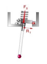
probe alignment, see figure 9. The touch probe can be described as having
low and high force directions when capturing a trigger, see figures 10 and
11.
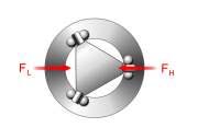 |
 |
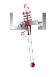 |
| figure 9, Force Direction |
figure 10, High Force Dir. |
figure 11, Low Force Dir. |
Stylus lengths will add additional error to your system. A short length of
about 10mm will not influence your data points, however a 100mm length will
increase the error 10 fold to the lobe deviation. If you need to extend your
stylus, we recommend the Renishaw PEL family of extensions. These are
extensions that mount between the probe head and probe body.
When the Trigger Force pressure is set too high, the probe error will
increase exponentially! Most mechanical probes allow you to adjust the
tension applied to the trigger mechanism, see manufacturers technical
manual. Some touch probe models, such as the Renishaw TP20, offer
interchangeable modules with a preset trigger force. By increasing the
pressure, you force the probe to trigger at a higher pressure that
introduces stress and deflections in the stylus tip and extension.
Strain-gauge or piezo designed probes, such as the Renishaw TP200,
minimizes the lobe error by eliminating the mechanical kinematics design.
However, these gauges are susceptible to speed changes and the actual
contact speed should be stable and consistent. Probes that use this
technology should not be considered for manual CMMs.
Operator Influences
Finally the operator will provide the greatest error. If the operator
captures data points with an inconsistent speed, repeatability errors are
introduced. To test for speed difference, lock the Z and X-axes on your CMM.
Place a part on your CMM and measure a +Y point. Increase the speed at which
your capture points. At a certain speed you will begin to see variances in
the reported results.
Other operator related issues include where you hold the CMM. If you have
a large CMM, probing while holding the probe bar just above the probe will
act differently that when you are holding as far up the probe bar as
possible. The probe bar is a lever, and by moving that lever you are placing
strain on the superstructure of the CMM. If you gather data points before
the CMM has ‘settled’ you will get unreliable data points.
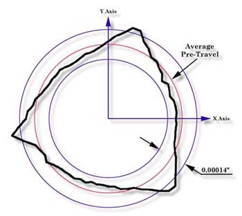
Data Point Spread
When measuring multi-point features, how you spread the data points will be
the single greatest influence on the accuracy and repeatability of the
feature. For example, if you capture data points on a circle using only a
15° sweep, the results are unreliable and not repeatable. If those same
points were captured over a 300° sweep, the results would be accurate, see
figure 12. The same holds true for Planes spheres, cylinders and cones.
Cylinders and cones require a proper spread over the length otherwise the
axis of the feature will not be reliable.
|
Arc (degrees) |
Center error |
Radius error |
| 180 |
0.00014 |
0.00000 |
| 120 |
0.00028 |
0.00014 |
| 90 |
0.00048 |
0.00034 |
| 60 |
0.00104 |
0.00090 |
| 30 |
0.00409 |
0.00395 |
| 20 |
0.00914 |
0.00899 |
| 10 |
0.03549 |
0.03535 |
| 5 |
0.12823 |
0.12810 |
| figure
12, Circle
deviations from reduced sweep arc |
Imagine capturing two points on a line only .25” apart with a probing error
of .0001”. The resulting line would have a repeatability error of .040” over
5.000” or 0.4584 degree! If that line were used as part of the Part
Coordinate System, then all subsequent features would have questionable
accuracy.
|


