Tolerance - Plane Features

Up

Back


Tol. Home


Site Map


helmel.com

Introduction

Geomet applies tolerance to Line features which is limited to Bilateral / Linear. To understand the basics of tolerance, please refer to Introduction to Tolerance in Geomet.

Plane Features

Tolerance of Plane features is limited to Cartesian / Linear. The value reported by a Plane is where the intersection with a PCS axis takes place and is considered 1 dimensional. Therefore only bilateral tolerance inputs are allowed.

PlaneTol.jpg (21556 bytes)
figure 1, 2D Line Tolerance

To activate the tolerance tool  see Working with Geomet Tolerance Windows

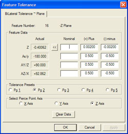
Figure 1  shows the 2D Line Tolerance dialog which allows nominals entered for position and corresponding angle. To better understand how these formats are used and interpreted, refer to Introduction to Tolerance.

NOTE: When applying a tolerance to Plane features it is possible to switch the reported pierce axis. If figure 1 in the "Select Pierce Point Axis" group, you can switch between X, Y or Z PCS axis.


Tolerance State On / Off, Tolerance Format, Process Control Tolerance, Out-of-Tolerance Flash Message