Most CMMs offer a machine coordinate system that is true to the working surface. This
allows the operator to establish simple, and fast, part coordinate system by eliminating
steps normally required to ensure accurate alignments. The following example assumes the
part orient in the Z axis is parallel to the Z axis of the CMM and the cylinder of the
GeoWidget is pointing in the -X direction.
Step 1
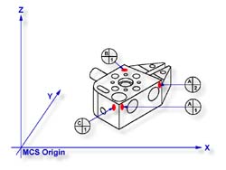
Request a -X Point feature
<4>, You will then be
prompted to "Measure -X Point". Capture points A-1 and A-2, refer to Figure
1. Note: if your system is active for auto-direction sensing then your prompt will
display "Measure Auto-Dir Point". See
System Options for controlling
Auto-Direction Sensing.
Step 2
Select Align
<j>. Note: when you elect to perform an
alignment without first establishing the orient, Geomet will assume the orient axis is
parallel to the machine coordinate system. For example, aligning in the XY plane will
force the Z axis of the MCS to establish the Z axis of the ICS.
Step 3
Select Origin <l>. This will establish the X origin as defined by the selected
direction of the -X Point features. Note: always perform the alignment prior to origin as
the alignment will effect the probe compensation on features such as 1D Points.
Step 4
Request a -Z Point feature <2>, You will then be prompted to "Measure -Z
Point". Capture point B-1.
Step 5
Select Origin
<l>. This will establish the Z origin and
your PCS Setup Guide will now reflect that only the Y origin is still required.
Step 6
Request a +Y Point feature <9>, You will then be prompted to "Measure +Y
Point". Capture point C-1.
Step 7
Select Origin <l>. This will establish the Y origin and complete the ICS to a
full part coordinate system. The PCS Setup Guide will disappear and you are now ready to
take feature measurements.
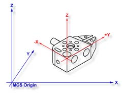
With a minimum of four data points and four command
requests administered in the proper sequence you have completed a full part coordinate
system, see figure 2.
|
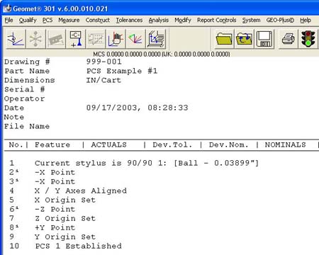 |
| figure 3, Final Inspection Report |
This method of establishing a PCS is not meant to work with
all production parts, but it does work with parts that have a surface that is capable of
providing the orientation, or primary datum, and can lay flat on your CMM.