Step 1
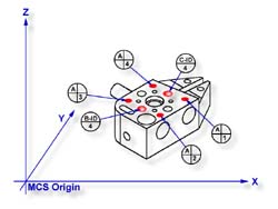
Request a -Z plane
<b>, if auto-direction is not
activated, you will be prompted for the probing direction which you should select as -Z.
You will then be prompted to "Measure -Z Plane", (if auto-direction is active
"Measure Auto-Dir Plane"). Capture points A-1, A-2, A-3 and A-4 as shown in
figure 1
Step 2
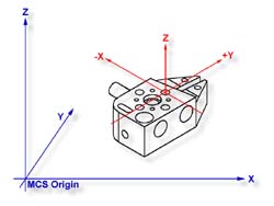
Select Orient
<j>. The orient command will create the
primary datum on the axis that is most normal to the machine coordinate system. For
example, if the plane used by orient was determined to be a XY plane then the normal will
most closely align with the Z axis. In your PCS Setup Guide, the Z Axis will be signed
off.
Step 3
Select Origin
<l>. This will establish the Z origin
which is determined by the normal direction of the -Z plane.
Step 4
Select Circle
<z>, if auto-direction is not activated,
you will be prompted for the Circle type, ID OD IR OR, choose ID. Capture the four data
points identified as B-ID/4, see figure 3.3a. Continue with the data points for the next
circle, C-ID/4.
Step 5
Select Align
<k>. Your ICS will update to include the
secondary datum which is derived from the two XY circles. The alignment takes place
through the reported XY position of the circles which are projected into the orient plane.
Step 6
Select
Origin <l>. Circles, which are 2D,
provide two directions when establishing an origin. In our example, the circle can be used
for the X and/or the Y directions. The origin command will prompt you whether to use the X
and then the Y. For our example you should answer Yes to both requests. Upon completion,
you will have established PCS 1.
In this exercise, we utilized two coplanar XY features for the alignment and subsequent
origin, see figure 3.
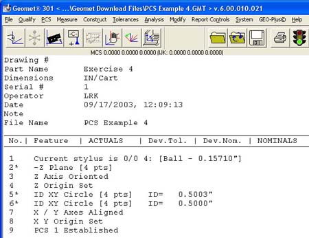 |
figure 3, Final Inspection Report |
As with many feature characteristics, the circles could have been replaced with
any feature that reports a 2D solution. These include 2D points, cylinder and cone pierce
points, etc. Through the proper selection of features, you can establish a part coordinate
on nearly any type of manufactured part.