Step 1
From the established PCS as defined in PCS Example #5, recall feature number 6 ID XY
Circle. We perform this step in preparation of the realignment. The offset align required
two features which both must be in the same PCS and stacked together in the report, see
Recalling Features.
Step 2
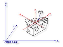
Select Circle
<z>, if auto-direction is not activated,
you will be prompted for the Circle type: ID, OD, IR, or OR, choose ID. Capture the four
data points identified as A-ID/4, see figure1.
Step 3
Select Offset Align, press
<shift + K >.
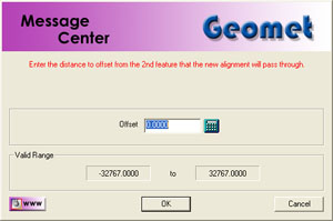
Note: Junior Users
if you do not have the Advanced PCS and Stylus option, you will be prompted whether to
realign PCS 1 or cancel, select < Ok >. A request will be displayed where you enter
your offset value. Enter .70711 and press < Accept >.