In this exercise, you will utilize Geomet’s automatic part coordinate system tool,
known as the Quick PCS. Quick PCS requires that you have auto-direction capabilities and
that it is active through System Options.
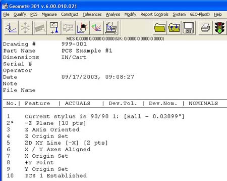
The premise of Quick PCS is to perform the basic Plane and 3 - 1D Point setup to create
a PCS without the operator commanding any feature requests. When you start Geomet and
establish the working stylus, Geomet is waiting for a data point. If it acknowledges an
incoming data point and is not currently setup for a feature, it assumes you are invoking
the Quick PCS option.
Step 1
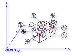
Using the datum targets as shown in figure 1, gather data points A-1 through A-4.
Geomet will automatically establish a
plane, orient and origin
after the forth point has been captured.
Step 2
Gather data points B-1 and B-2 making sure you follow the rules on probing 1D points
using auto-direction, see
Measured Features - Points.
Once these two points are captured, Geomet will establish the alignment and origin based
on the point directions.
Should the points be captured in such a way as to misidentify the direction, the Quick
PCS tool will abort the auto sequence and return you to normal inspections. If this
occurs, correct the point direction (see
Measured Features - Points) and continue
with the setup as described in exercise 2, steps 5 - 8.
Step 3
Capture the final data point, C-1 and Geomet will complete the final origin and
establish PCS 1.