Points are dimensionless locations is 3D space. Points have no size. The location of a
point is specified by its X, Y, and Z coordinate in a particular coordinate system. There
are many points that Geomet support. These include 1D, 2D and 3D points.
1D Points have 1D locations. There are 6 1D point routines, designated ±X, ±Y and
±Z. Pressing one of these keys prepares Geomet to measure a single point on a planar
surface, followed by a printout of the location of the center of the stylus corrected by
the stylus radius in the PCS probing direction. Problems arise if the planar surface is
not parallel to a PCS base plane.
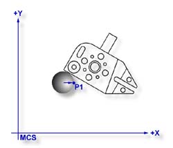
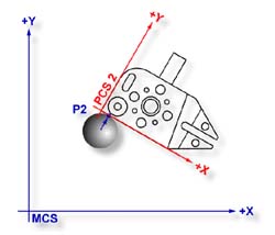
Figures 1 and 2, illustrate a 1D point measurement of one and the same planar surfaces
prior to alignment (MCS) and after alignment (PCS 2). Although the stylus center is at the
same XYZ location in both cases, the calculated points P1 and P2 are quite different. P1
resulted from a probe radius correction parallel to the X axis of the MCS. P2 resulted
from a probe radius correction parallel to the Y axis of PCS 2. This illustrates how
measurements of a surface in an unaligned PCS can produce erroneous results.
Single 1D Point measurements can only be used to determine the locations of planar
surfaces which are parallel to the PCS planes. Pairs of 1D Point
measurements on planar surfaces which are parallel to PCS planes may serve to determine
the Distance between the surfaces or the location of the Bisector of surfaces. Pairs of 1D
Point measurements on simply skewed planar surfaces, meaningless in themselves, may be
used to define a Line on a surface or to Align the current PCS to be parallel to the
surface.
Single and multiple 1D Point measurements on compound skewed plane or curved surfaces
provide meaningless data.
To measure a 1D Point, press the corresponding Point direction key and gather a data
point on your work piece. If you have
Auto-Direction enabled,
you will be prompted "Measure Auto-Dir Point" and your approach vector to the
work piece will identify the probing vector.
Tolerance of 1D Points is limited to
Cartesian / Linear.
1D Points are available for use in building Part Coordinate Systems. Single 1D points
can establish the origin for a single PCS axis. For example: a +X Point can establish the
X axis origin. Two coplanar 1D Points can establish an alignment.