|
|
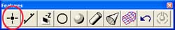
Command Activation
| 1,2,3,4,5,6,7,8,9 |
Measure→Point |
 |
| Keyboard |
Main Menu |
Toolbar |
|
Feature measurement point types |
|
1D Point |
+/- X, Y and Z Reported Directions. Cartesian only. |
2D Points
IR/OR 2D Points |
Reported in PCS Base Planes XY, YZ, ZX. Can be
Cartesian or Polar. Special cases include Inside and Outside Polar
Points. |
Point - 3D
IR/OR 3D Points |
Reported as XYZ. Can be Cartesian or Polar. Special
cases include Inside and Outside Polar Points. 3D Points are not
compensated for the probe radius when using a standard electronic
touch probe. IR and OR 3D Points are compensated one probe radius
from the PCS Origin. |
|
Point - Vector |
Surface 3D Points. Compensated by one probe radius
along the defined IJK surface vector. Vector Points can be created
and measured using a ASCII import table. |
Definition
Points are dimensionless locations is 3D space. Points have no size. The location of a
point is specified by its X, Y, and Z coordinate in a particular coordinate system. There
are many points that Geomet support. These include 1D, 2D and 3D points.
Measured points consist of 1D, 2D and 3D style geometric elements. keyboard access to
these points are done through the number keypad, see table 1.
|
Keystroke |
1D Point |
2D Point |
3D Point |
|
1 |
-Z |
|
|
|
2 |
-Y |
|
|
|
3 + 2 |
|
XY IR |
|
|
3 + 4 |
|
ZX IR |
|
|
3 + 6 |
|
YZ IR |
|
|
3 + 9 |
|
|
3D IR |
|
4 |
-X |
|
|
|
5 + 2 |
|
XY |
|
|
5 + 4 |
|
ZX |
|
|
5 + 6 |
|
YZ |
|
|
5 + 7 |
|
|
Vector Point |
|
5 + 9 |
|
|
3D |
|
6 |
+X |
|
|
|
7 + 2 |
|
XY OR |
|
|
7 + 4 |
|
ZX OR |
|
|
7 + 6 |
|
YZ OR |
|
|
7 + 9 |
|
|
3D OR |
|
8 |
+Z |
|
|
|
9 |
+Y |
|
|
|
IR
= Inside Radius / OR = Outside Radius |
| table 1, Keyboard Access |
2D Points
Definition
The 2D Point function is normally used in conjunction with a hard taper probe for
simple contact determination of the location of bores whose axes are parallel to the PCS Z
axis. It can also be used with hard ball stylus for single contact determination of the
location of bores whose axes are parallel to any PCS axis. In these applications the 2D
Point feature is referred to as the self-centering routine.
The 2D Point feature can also be used with hard or electronic trigger ball stylus to
create 2D Bisector Point features in slots or a web for Aligning purposes as shown in
PCS Example #6. All 2D Points are automatically projected into the
requested PCS base planes. The example shown in figure 3, demonstrates the use of 2 - 2D
Points on the outside of the GeoWidget bisected to obtain a 2D Point on the centerline of
the body.
Measured features that create a 2D point entity include the
4
Point Intersect, Slot / Web and Oval Slot Macro Features.
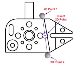 |
| figure 1, 2D Bisect Point |
To measure a 2D Point press the 2D Point key, < 5 > from the number pad. Geomet
will prompt you for a PCS base plane the 2D Point will project into, see table 1 above.
Choose XY, YZ or ZX and begin your measurement.
Tolerance of 2D Points is available in
Cartesian, Polar or RFS Positional Tolerance formats.
Definition
The IR (Inside Radial) and OR (Outside Radial) Point features allows 2D, ball radius
compensated probing of cylindrical surfaces. The probe vector is determined as a vector
from the current PCS origin through the ball center of the stylus. Inside Radial features
are compensated by adding one radius along this vector, Outside Radial subtracts one probe
radius, see figure 2.
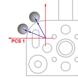 |
| figure 2, Outside Radial Point |
These features are ideal for measuring extremely large radial surfaces that only offer
a small segment to capture data points on. Translate your PCS origin to the centroid of
the radial feature and capture radial points along the surface.
Tolerance of 2D Points is available in
Cartesian, Polar or RFS Positional Tolerance formats.
|
| |
|
|


