|
Command Activation
| 1,2,3,4,5,6,7,8,9 |
Measure→Point |
 |
| Keyboard |
Main Menu |
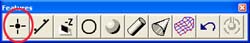
Toolbar |
|
Feature measurement point types |
|
1D Point |
+/- X, Y and Z Reported Directions. Cartesian only. |
Point - 2D
IR/OR 2D Points |
Reported in PCS Base Planes XY, YZ, ZX. Can be
Cartesian or Polar. Special cases include Inside and Outside Polar
Points. |
Point - 3D
IR/OR 3D Points |
Reported as XYZ. Can be Cartesian or Polar. Special
cases include Inside and Outside Polar Points. 3D Points are not
compensated for the probe radius when using a standard electronic
touch probe. IR and OR 3D Points are compensated one probe radius
from the PCS Origin. |
|
Vector Points |
Surface 3D Points. Compensated by one probe radius
along the defined IJK surface vector. Vector Points can be created
and measured using a ASCII import table. |
Definition
Points are dimensionless locations is 3D space. Points have no size. The location of a
point is specified by its X, Y, and Z coordinate in a particular coordinate system. There
are many points that Geomet support. These include 1D, 2D and 3D points.
Measured points consist of 1D, 2D and 3D style geometric elements. keyboard access to
these points are done through the number keypad, see table 1.
|
Keystroke |
1D Point |
2D Point |
3D Point |
|
1 |
-Z |
|
|
|
2 |
-Y |
|
|
|
3 + 2 |
|
XY IR |
|
|
3 + 4 |
|
ZX IR |
|
|
3 + 6 |
|
YZ IR |
|
|
3 + 9 |
|
|
3D IR |
|
4 |
-X |
|
|
|
5 + 2 |
|
XY |
|
|
5 + 4 |
|
ZX |
|
|
5 + 6 |
|
YZ |
|
|
5 + 7 |
|
|
Vector Point |
|
5 + 9 |
|
|
3D |
|
6 |
+X |
|
|
|
7 + 2 |
|
XY OR |
|
|
7 + 4 |
|
ZX OR |
|
|
7 + 6 |
|
YZ OR |
|
|
7 + 9 |
|
|
3D OR |
|
8 |
+Z |
|
|
|
9 |
+Y |
|
|
|
IR
= Inside Radius / OR = Outside Radius |
| table 1, Keyboard Access |
Definition
A Vector Point provides the capability to measure the deviation from nominal of a
target point on any arbitrary surface, given the XYZ location of the 3D target and the
nominal unit vector components I, I, and K at the target.
Geomet Vector Point Modes
Geomet offers several modes to capture Vector Points. Each mode is designed to enhance
your ability to capture surface data points from all or some known data. These methods
are:
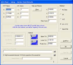
To activate the Vector Point screen, press the <5 + 7> keystroke on the
number keypad.
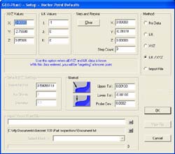 |
figure 1,
Vector Point Screen, Manual Version |
Vector Point Technical Discussion
To better understand the application of Vector Points, please refer to
Technical Note #1, "Curved Surface Measurement with Vector
Point".
While the percentage of Geomet users who have made extensive use of the vector point
function is small, some have come to regard it as indispensable, and every now and then
another Geomet owner discovers the wonders of vector point. Invariably, this discovery is
followed by about two weeks of daily and lengthy phone conversations between the user and
our application support engineers, during which the workings and benefits of the function
gradually become clearer to the user. In an attempt to shorten this process, we have
written a Technical Note, "Curved Surface Measurement with
Vector Point", that contains a description of its workings and some suggested
experiments that might be used to gain familiarity with the problems of curved surface
measurement on a manual CMM. This technical note is long and likely boring for anyone
without a serious interest in the problem.
Should your interest in vector point survive the reading of that technical note, you
may also be interested in another Technical Note, this one titled, "Automatic
Generation of Vector Points for DCC CMMs". This note details the process used to
create a working solution to capture large vector point data clouds on complex surfaces.
Tolerance of Vector Points is
available in Cartesian, Polar or RFS Positional Tolerance formats.
Vector Point Reporting Format
All Vector Point methods provided by Geomet are designed to give the operator the
greatest flexibility to capture vector points with varying known data. The reporting
characteristics of vector points remain the same for all methods used.
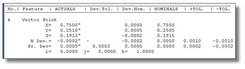 |
| figure 2, Vector Point Report |
In the vector point report, the XYZ actual surface point values, nominal deviation and
linear deviation from nominal are shown under the Actuals, Dev. Nom. and Nominals
columns respectively. Additional data reported include Normal Deviation (N
Dev.) and Probe Deviation (Pr Dev).
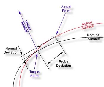 |
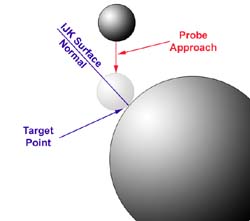
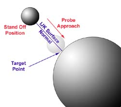
| figure 3, Normal / Probe Deviations |
Normal Deviation is the deviation along the Vector Normal from the actual data point.
When applying a profile tolerance on a arbitrary surface, the Normal Deviation reports
where in the profile band the actual point resides.
Probe Deviation is the distance from the actual data point to the axis of the Vector
Normal. This value provides a understanding on the quality of the actual data point
against the expected target point. Under normal conditions, this value should be small,
but can be adversely affected based quality of the drive along the Vector Normal approach.
Using Vector Point Tools
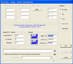
To begin, we will start with Method 4, where the XYZ Nominal Target and IJK Normal
Vector are known, as shown in figure 1 under the Method group.
This method requires that you know the XYZ target and the IJK surface vector normal at
that target point. In our examples, we will utilize a 1" diameter reference sphere.
Start by establishing a XYZ Origin on the center of the sphere. Utilize the orient and
alignment of the MCS by creating a PCS with the
ICS→PCS
function.
Step 1
Enter the nominal XYZ target and the IJK normal vector values.
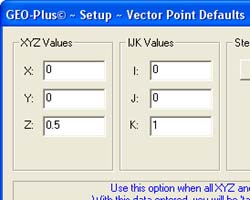 |
| figure 5, Enter XYZ / IJK Values |
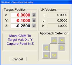
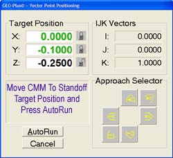
Step 2
Press the <Ok> button or press the <enter> key on the keyboard. The Target
Positioning dialog will show where the probe is currently in relationship to where the
probe should be to capture the vector point.
 |
 |
| figure 6, Target Window |
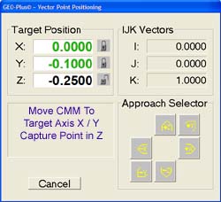
figure 7, On Target Positions |
In figure 6, the distance to the position the CMM is required to be at
is shown under Target Position. In this example, there are symbols next to X and Y showing
a "closed lock". These are the suggested axis Geomet has determined you should
move and lock over the targeted XYZ point. Should access to the target point be limited
where another axis must be used to approach the target, select the desired direction in
the Approach Selector group. The lock symbols and target values will update based on your
selection.
NOTE: If the Digital Readout is activated, the DRO will
display the Targeting Position to allow better visual appearance at a greater distance.
NOTE: The color of the XYZ Targeting display
showing on position can be adjusted, see Geomet
System
Options.
 |
| figure 8, Manual Target Approach |
Locate the probe over the target axis specified, lock the CMM with the axis locks and
use the fine adjust knobs until the X and Y values approach 0.0000". When inside the
allowable position values as determined by the probe deviation, the readout will turn
green in color as shown in figure 7.
Next, carefully move the probe down along the -Z axis until you come in
contact with the part, see figure 8. Geomet will capture that point and report
the actual XYZ location and deviations.
Upon completion, the vector point routine will return to the main vector point dialog
for additional instructions.
Step 1
 |
|
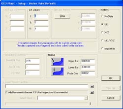
| figure 9, Vector Point, DCC Version |
figure 10, Enter XYZ / IJK Values |
Enter the nominal XYZ target and the IJK normal vector values, see
figure 10.
Step 2
 |
| figure 11, DCC Target Dialog |
Press the <Ok> or <AutoRun> button or press the
<enter> key on the keyboard. The Target Positioning dialog will show where the probe
is currently in relationship to where the probe should be to capture the vector point,
see
figures 11.
 |
| figure 12, DCC Approach Vector |
Move the CMM teaching
IPs
until you are over the expected Stand Off,
SO,
on the approach vector. Press the <AutoRun> button and the CMM will reposition over
the expected target point along the IJK surface normal vector at the standoff location,
see
figure 12. When at the stand off location the probe will commence to capture the
vector point driving down the surface normal vector.
NOTE: The accuracy of moving along the approach vector is greatly influenced by the
speed of approach and length of approach. To obtain the greatest control, it is better to
have a slower approach speed which is controlled by the probing speed and is set in the
DCC Options page. To increase the approach distance, the value can be set on the Vector
Point page and is shown in figure 8.
Method 1 offers the user a chance to obtain approximate IJK and arbitrary target data
build tools. This method is most likely to provide good results of planar surface in any
orientation. It is designed to allow the operator to perform a IJK approximation by
gathering 3 - 5 data points from which Geomet will calculate a IJK to be used as the
Vector Normal.
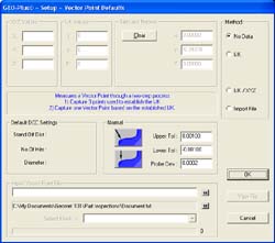 |
| figure 13, Method 1 - No Known Data |
To begin Method 1, select the "No Data" choice in the Method group. the
Vector Point tool will reconfigure itself as shown in figure 13. The only data that can
now be entered is the Upper / Lower Tolerance and Probe Deviation.
Step 1
To begin the measuring process, press the <Ok> button. The Vector Point tool will
disappear replaced with a message in the Geomet Prompt area stating "IJK
Approximation" and a countdown of 3.
Capture 3 data points surrounding the target area for the vector point. These points
should be sufficiently spaced apart to assure confidence that the captured data points
will solve the algorithm for a plane. Should the points be too close together, an error
can be introduced caused by the influence of the repeatability of the touch probe and CMM
structure. If the surface you are working with is a known flat plane, spread the data
points out.
Step 2
After the IJK Approximation data points have been captured, the Geomet prompt will now
display "Measure Vector Point". Capture the vector point.
Geomet will cycle back to Step 1 waiting for the next IJK Approximation.
DCC CMM application of Method 1
Performing Method 1 on a DCC style CMM offers a greater degree of accuracy on arbitrary
surfaces. The process still requires an IJK Approximation which becomes a process that the
CMM will perform.
 |
 |
| figure 14, DCC Method 1 |
figure 15, Capture Target Point |
Step 1
As seen in figure 14, the Default DCC Settings group is available when the CMM is a DCC
style. Enter a proper standoff distance for the vector point. Enter a number of points to
be used to determine the IJK Approximation in the control labeled 'No. of Hits".
Acceptable value for number of hits is 3 - 5. Enter a diameter value the CMM will use to
capture the IJK Approximation points. Normally a small diameter such as 0.3" works
well. Press the <Ok> button to proceed.
Step 2
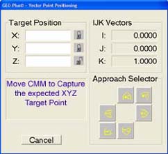
The Vector Point Positioning dialog will appear, see figure 15. You are now
instructed to capture the target vector point on the surface.
 |
 |
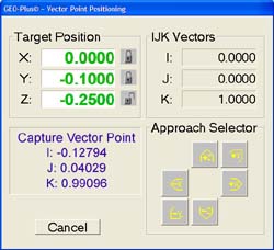 |
figure 16,
Start Approximation |
figure 17,
Calc Approximation |
figure 18,
Capture Vector Point |
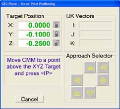
Step 3
When the target point has been captured, you are instructed to move the probe over the
target point and press the <IP> button on the joystick.
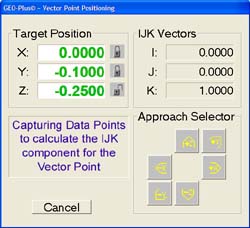
Step 4
The CMM will calculate a motion path based on the diameter and number of hits required
for the IJK approximation. The CMM will then capture the data points under DCC control,
see
figure 17.
Step 5
When the IJK Approximation has been completed, the CMM will move to the stand off
position on the new vector normal and capture the target vector point to complete the
process, see figure 18.
Method 2 offers the user a chance to obtain vector points on surface that have a known
IJK surface normal. This method is designed for use on planar surfaces and can be used to
capture many vector points quickly.
 |
| figure 19, Method 2 Known IJK |
Step 1
Enter the known IJK values in the edit controls and press <Ok>
Step 2
Geomet will prompt you to capture vector points on the designated surface. Upon
capturing the data point, Geomet recycles step 2.
DCC CMM Application of Method 2
Method 2 on a DCC style CMM requires the same steps as on the manual CMM. Please refer
to Steps 1 and 2 listed above. It is important that a proper motion path is built by using
a proper stand off distance and IP points between vector points.
NOTE: Method 3 is only available on DCC style CMM and will be disabled on manual CMMs.
This method requires that the target XYZ position of the vector point be supplied.
Geomet will build from that target an IJK approximation by capturing data points on a
diameter path around the target point and calculating an IJK vector normal.
 |
|
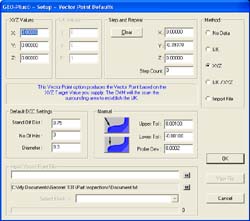
| figure 20, Method 3 Vector Point |
figure 21, Start IJK Approximation |
Step 1
As seen in figure 20, the Default DCC Settings group is available when the CMM is a DCC
style. Enter a proper standoff distance for the vector point. Enter a number of points to
be used to determine the IJK Approximation in the control labeled 'No. of Hits".
Acceptable value for number of hits is 3 - 5. Enter a diameter value the CMM will use to
capture the IJK Approximation points. Normally a small diameter such as 0.3" works
well. Press the <Ok> button to proceed.
Step 2
The Vector Point Positioning dialog will appear, see figure 21. You are now
instructed to position the CMM probe over the target point and press the
<IP> button
on the joystick.
|
|
|
| figure 22, Capturing Data Points |
figure 23, Capturing Vector Point |
Step 3
The CMM will now calculate a motion path based on the IJK Approximation diameter and
number of hits centered on the target point and execute data point capturing,
see
figure 22.
Step 4
Once the IJK Approximation has been calculated, the CMM will move to the stand off
point above the targeted vector point and commence capturing the actual data point,
see
figure 23.
Method 5, when chosen sets Geomet up to read in an ASCII Vector Point data file that
contains all necessary targeting, vector normal and motion commands to measure vector
points.
Microsoft Excel and Microsoft WordPad has be used to demonstrate how to build ASCII
files to be used in Vector Point import. The samples are available for download below.
When building a table, Geomet uses keywords followed by a parameter list which describes a
operation. These keywords can be found in the
Vector Point Import Table.
Vector Point ASCII Table
The table is made up of 2 main sections. These are the Header and Block Descriptions.
The Header is data that can set a global setting for use by all Blocks. Block Descriptions
contain the actual targeting data and supporting tolerance, motion, probe and text data.
Keywords used in the table are not upper or lowercase sensitive and can be entered in
either. Geomet always interprets keywords in uppercase and performs the operation
automatically.
Vector Point ASCII Table Header
The header has limited keywords that control the global settings for their respective
features.
| Keyword |
Description |
| U: |
Unit of Measurement |
| S: |
Stand Off Distance |
| O: |
Over Travel Distance |
| H: |
Upper Tolerance Value |
| L: |
Lower Tolerance Value |
| E: |
Probe Deviation |
An example of a header would be:
| U: |
Inch |
| S: |
0.50 |
| O: |
0.50 |
| H: |
0.001 |
| L: |
-0.001 |
| E: |
0.0002 |
Should any of the header items be missing from the ASCII import file,
Geomet will prompt for a starting value when the file is opened. This does not apply
to Unit of Measure. The keywords shown above can also be used in Block Descriptions.
Vector Point ASCII Table Block Descriptions
An imported data file can contain many blocks of data defined by a 'start' and 'stop'
keyword. This allows organization of common Vector Points. For example; a block of vector
points may contain all necessary points required for the top surface of the part being
inspected. A second block can be used to group all vector points for the front surface.
The process of building blocks of data can be helpful for use on DCC style CMMs. By
grouping all common vector points, an auto run through the list can be done without
concern of positioning the probe around corners or other obstacles. In example #3, we show
how mixing vector points with interim points (IP) to create a complete motion path to
capture data points on more than a side of the GeoWidget. Another use of blocks can be to
group all common tolerance bands together.
A block is always started by the keyword "start" followed by vector point
instructions and always ends with a "stop". An example might look like:
| START |
|
 |
|
Keywords / Instructions...... |
|
Keywords / Instructions...... |
|
Keywords / Instructions...... |
| STOP |
|
Vector Point ASCII Table Creating in Excel
Creating the Vector Point ASCII data file in Excel is one method used where the power
of a spreadsheets internal math functions can assist in developing the targeting tables.
For example, should you want to create a table of vector points that covers a large
area using a uniform grid of rows and columns, Excel would be used with the fill range
tools or copying formulas. In
sample #4, you will see the
spreadsheet uses formulas to step the vector points in a column by changing the Y target
value, 0.25" between each point.
Vector Point ASCII Table Saving Data Files
Saving the spreadsheet in a form that Geomet will read can be accomplished by saving in
either file type:
- Formatted Text (Space Delimited)(*.prn)
- Text (Tab delimited)( *.txt)
To save into one of these formats, from Excel use the drop down menu
[File→Save As],
see
figure 24.
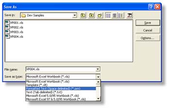 |
| figure 24, Excel File Save As Options |
Choose one of the acceptable formats (*.prn) or (*.txt) in the "Save as type"
drop down selections. Once the file type has been chosen, select <Save> and Excel
will prompt you with a warning that not all formatting can be saved in this file type.
Accept the warnings and continue saving.
Vector Point ASCII Table Keyword Reference Table
Each keyword used in the Vector Point data file utilizes a fixed syntax for proper
application. In some cases there are more than one syntax for a keyword. The tables below
help to demonstrate the proper application.
keyword START
Identifies the beginning of a block. Must have a STOP keyword
associated at the end of the block. There are no parameters following the keyword.
usage START
keyword STOP
Identifies the end of a block. Must have a START keyword associated at
the beginning of the block. There are no parameters following the keyword.
usage STOP
keyword N:
Used within the START and STOP keywords to attach a
label to the block. There should be only 1 N: associated with each block.
The naming of a block is optional and should there be no name included, the label for the
block will be a sequential number starting with 1.
usage N: Top Surface of GeoWidget
keyword U:
Unit of Measurement. Prepares the data to be imported and reported in metric or inch
modes. This does not place a record in the current inspection report.
usage U:metric, U:mm, U:inch
keyword PROBE:
Activates a requested stylus. This feature will place a stylus record in the inspection
report.
usage PROBE: 2
keyword M: -or- TEXT:
Places a standard Geomet text statement in the inspection report.
usage M: Top surface of the GeoWidget
usage TEXT: Top surface of the GeoWidget
keyword H:
Establishes the upper limit for the Vector Point profile band. The value attached to
this keyword is sign sensitive.
usage H: 0.001
keyword L:
Establishes the lower limit for the Vector Point profile band. The value attached to
this keyword is sign sensitive. Should you require a profile band of +0.001 / -0.001 you
must enter -0.001 as shown below.
usage L: -0.001
keyword E:
Establishes the Probe Deviation or probing error limit. This value must be > 0.000.
usage E: 0.0002
keyword T:
Attaches Print Exception Tags on the reported Vector Point values based on the
parameters shown after the keyword. The available parameters are X, Y and Z used alone or
in any combination. for example, using the X alone will tag only the X reported value.
Using XZ or ZX will attach a tag to X and Z values.
usage T:XYZ
keyword IP:, IP=,
IP
=
Creates a Interim Point (IP) used during DCC operations to traverse between XYZ
locations. These values are entered in local Part Coordinate System values. There are 4
variants to entering Interim points, see usage.
An interim point has 3 values; X, Y and Z. The import filter will accept a space comma
or tab between the values.
|
usage |
X |
Y |
Z |
| IP: |
1.234 |
2.345 |
3.456 |
| IP= |
1.234, |
2.345, |
3.456 |
| IP = |
1.234 |
2.345 |
3.456 |
keyword X: Y: Z: I: J: K:, X= Y= Z= I= J= K=
Creates the Vector Point target. This is the expected point of contact on a nominal
surface. This value also is inserted in the tolerance nominal of the vector point being
created. These values are entered in local Part Coordinate System values. There are 4
variants to entering Interim points, see usage. NOTE: to ensure compatibility
with previous versions of Geomet, a target point can also be defined without any prefix
values. In these instances, the XYZ and IJK values are entered in s columns and extracted
into; column 1 = X, column 2 = y, etc.
An interim point has 3 values; X, Y and Z. The import filter will accept a space comma
or tab between the values.
| usage |
| 1.10 |
2.20 |
3.30 |
0.00 |
0.00 |
1.00 |
|
|
|
|
|
|
| 1.10, |
2.20, |
3.30, |
0.00, |
0.00, |
1.00 |
|
|
|
|
|
|
| X: |
1.10 |
Y: |
2.20 |
Z: |
3.30 |
I: |
0.00 |
J: |
0.00 |
K: |
1.00 |
| X= |
1.10 |
Y= |
2.20 |
Z= |
3.30 |
I= |
0.00 |
J= |
0.00 |
K= |
1.00 |
| X = |
1.10 |
Y = |
2.20 |
Z = |
3.30 |
I = |
0.00 |
J = |
0.00 |
K = |
1.00 |
keyword PROBESP:
Updates the current probe speed for use on DCC style CMMs.
Valid limits: 0.010" - 1.000" (0.254mm - 25.4mm)
usage PROBESP: 0.25
keyword TRAVSP:
Updates the current traverse speed for use or DCC style CMMs
Valid limits: 0.01" - 20.0" (0.254mm - 508.0mm)
NOTE: Some CMMs have internal limits on maximum traverse speeds maybe less than the valid
limit shown above.
usage TRAVSP: 10.0
keyword S:
Establishes the standoff distance for use with DCC style CMMs. This is the distance
along the vector point surface normal (IJK) above the expected target point where the
probe will position itself prior to commencing the measurement move to capture the XYZ
target. This point along the vector normal is referred as a Stand Off point and is
calculated at the time of executing the vector point data file.
The smaller the stand off distance, the greater chance of missing your target point.
This is caused by the instability of the vector motion approach from the stand off point
to the target point. The CMM will attempt to follow the IJK vector to the target point but
is influenced by the mass of the CMM, the speed prior to starting the probe move, the
speed of the probe move and the stability of the motor tuning. It is suggested, that a
minimum standoff distance of 0.50" and a slower probe speed of 0.20" be used in
all cases where possible.
One analogy to explain probe motion is to understand the physics of driving a car. Most
drivers when approaching a corner will slow down to make the turn smooth. However, should
you turn while driving too fast, your car will overshoot the expected turning radius. The
driver will then have to compensate to get back to the center of the turning radius, or
lane. The car will then overshoot the expected lane due to the mass of the car pushing
beyond the center point. The car will then sway back and forth while stabilizing toward
the center of the driving lane.
CMMs are no different. A heavy CMM will require slower speeds during tight turns or to
follow a projected path accurately.
usage S: 0.50
keyword O:
Defines the Over Travel distance the probe will travel past past the expected XYZ
measurement contact point. Should the probe movement reach this distance, all motion stops
as a safety precaution.
The over travel distance should be sufficient to allow safe passage of the probe
without allowing contact with the body or head of the probe.
usage O: 0.75
Vector Point ASCII Table Execution
When the vector point ASCII data file has been opened, the execution of that data will
be depend on whether you have a manual or DCC style CMM.
To execute, start by selecting the block from the data file in the drop down tool
labeled "Select Block->", see figure 25.
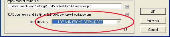 |
| figure 25, Select Vector Point Block |
To execute the vector point information contained in the block on a manual CMM, select
the <Ok> button from this dialog. The behavior of the targeting will be the same as
defined in
Manual Application of Method 4.
However, the vector point import tool will supply the XYZ and IJK values with every entry
in the data block.
Executing the vector point data file on a DCC system can be done in 2 methods.
Depending on the information in the vector point data file, you can choose to execute one
point at a time, or run the entire block.
Executing one point at a time allows the building of the motion map by manually
teaching the probe path and entering IPs by pressing the IP button on the joystick. Geomet
will provide a targeting box to the standoff point before the expected XYZ contact point,
as described in
DCC Application of Method 4.
To perform this method, press the <Ok> button. When each point has been completed,
the vector point import tool will advance to the next point in the data file and prompt
you to proceed with the next step.
Should you have data blocks that includes all information necessary to allow safe
transition of the probe between vector points, select the <AutoRun> button from the
dialog. This will execute all vector points in the data block. In
example #3, you will find a data block that contains all
motion required to move the probe around the GeoWidget safely and capture several vector
points.
|


