|
|
|
Command Activation
| shift + " |
PCS→ "ICS→PCS" |
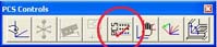 |
| Keyboard |
Main Menu |
Toolbar |
Introduction
The Interim Coordinate System (ICS) is a coordinate system that has not been completed to the status of a
Part Coordinate System (PCS). For
example, when Geomet begins a part inspection, the only coordinate system available is the
Machine Coordinate System (MCS). The MCS has no relationship to the part
that is placed on the CMM. It is then customary to establish a PCS on the
part being inspected for the alignment and XYZ origin correspond to nominal
data supplied either by a print, or CAD model.
Building a PCS normally starts with establishing an Orient on the part.
This would correspond to the Primary Datum of the Datum Frame Reference.
When you establish the Orient, Geomet maintains a partially completed
coordinate system behind the scenes. This coordinate system would not be
considered complete because the Alignment (Secondary) and Origin (Tertiary)
datums have not been established.
During the inspection process, reported results on features are hidden until
a PCS is
completed. Only then will the reported data be meaningful.
Definition
The ICS→PCS routine converts the status of an interim coordinate system from
interim to complete. The effect of this routine is to permit the user to obtain printed
results from what would normally be suppressed data.
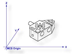 |
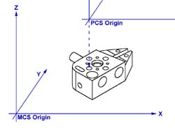
| figure 1, GeoWidget on CMM |
An example of using ICS→PCS might be used when establishing the first coordinate
system on a sample part such as shown in figure 1. In this example, we have the GeoWidget
laying on the surface plate of the CMM with the OD cylinder pointing in the -X direction.
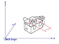
The required dimension to inspect is the distance between the two bores as shown in figure
2.
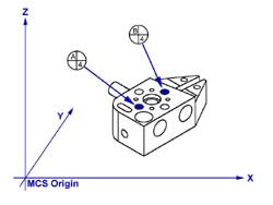
Step 1
Our first operation would be to measure the circle A/4 using an ID Circle, key
<z> followed by the ID selection, see figure 3.
 |
 |
 |
| figure 2, Dist. Required |
figure 3, Measure Circles |
figure 4, Completed PCS |
Step 2
Select Origin, <l> Geomet will prompt you to establish the X and Y origins which
you answer <Yes> to both. This will bring create a ICS with the X and Y origin in
the center of A/4.
Step 3
Select the ICS→PCS command, <shift + ">. This will bring forward
the Orient, Alignment and the Z origin from the ICS. A completed part coordinate system
will be established as shown in figure 4.
Step 4
Switch Geomet to Polar mode if it is not already there, key <e>.
Step 5
Measure circle B/4 using the circle command, <z>. The reported values will be
straight line values satisfying the requirements as shown if figure 2.
|
| |
|
|


