|
|
Plane - Cylinder - Circle
Introduction
In this exercise, we will create a part coordinate system utilizing a plane for the
orient and origin, a cylinder for the alignment followed by a circle for the last
components of the origin. The following example assumes the part is placed on your CMM
where the cylinder of the GeoWidget is pointing in the -X direction.
 |
 |
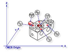
| figure 1, Datum target layout |
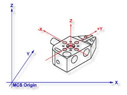
figure 2, Complete PCS |
Practice Steps
Step 1
Request a -Z plane
<b>, if auto-direction is not
activated, you will be prompted for the probing direction which you should select as -Z.
You will then be prompted to "Measure -Z Plane", (if auto-direction is active
"Measure Auto-Dir Plane"). Capture points A-1, A-2, A-3 and A-4 as shown in
figure 1.
Step 2
Select Orient
<j>. The orient command will create the
primary datum on the axis that is most normal to the machine coordinate system. In your
PCS Setup Guide, the Z Axis will be signed off.
Step 3
Select Origin
<l>. This will establish the Z origin
which is determined by the normal direction of the -Z plane.
Step 4
Select Cylinder
<c>, if auto-direction is not
activated, you will be prompted for the cylinder type, ID OD IR OR, choose OD. Capture the
six data points identified as B-OD/6, see figure 1.
Step 5
 |
|
figure 3, Select Axis |
Select Align
<k>. A cylinder offers the possibility of
more than one alignment solution. In our example, you have solved the Z axis orient by
utilizing the previous plane, therefore you are attempting to align the remaining axis, or XY. Select the XY button from the Select Axis dialog, see figure 3.
Your ICS will now update to include the secondary datum which is derived from the
longitudinal axis of the cylinder. In this example, the cylinder was reported as piercing
the YZ ICS base plane, therefore the normal to that plane is X with a direction of -X. The
PCS Setup Guide will update to reflect the XY Axis have been solved.
Step 6
Select Circle, if auto-direction is not activated, you will
be prompted for the Circle type, ID OD IR OR, choose ID. Capture the four data points
identified as C-ID/4, see figure 1.
Step 7
Select Origin. the Circle, which is 2D, provide two
directions when establishing an origin. In our example, the circle can be used for the X
and/or the Y direction. The origin command will prompt you whether to use the X and then
the Y. For our example you should answer Yes to both requests. Upon completion, you will
have established PCS 1, see figure 2
Final Inspection Report
There are times when you are required to utilize more
than one 3D feature to solve for the part coordinate system. In this example we used a 3D
feature, a cylinder, from which the alignment is derived, therefore you are prompted to
solve which part coordinate system component to solve.
 |
|
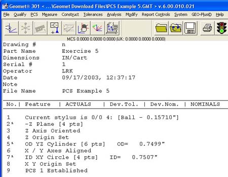
figure 4, Final Inspection Report |
From this example you should note that the data point spread on the cylinder is
approximately 1.25"in the X axis and the width of the part is 4.50". This can be
a cause of concern as it is poor inspection practice to have your data point spread ratio
to the width of the part less than 50%, in this case only 28%. The possibility of skewing
your part coordinate system increases dramatically as your ratio is reduced.
However, conditions do arise that do not allow for proper setup and as the inspector,
you are challenged to determine the best data point spreads with the features available
that will produce a sound part coordinate system.
Related Procedures:
Download PCS Example #5 (.zip)
Go to PCS Examples:
prev
1
2
3
4 5
6
7
8
9
10
11
12
next
Orient,
Align,
Origin,
Plane,
Cylinder,
Circle
|
| |
|
|


