|
|
Pivot Alignment
Introduction
In this exercise we will perform a realignment of the current PCS by pivoting around
the origin through the last measured or recalled feature. The pivot function performs a
realignment of an existing part coordinate system. As you must have a complete coordinate
system defined, please setup your part described in PCS Example #5.
|
Notice to Junior Users! |
|
If you do not have the Advanced
PCS and Stylus Option, you have access to only one PCS at any point of your
inspection. By performing the Pivot align command, you will realign the existing PCS 1 and
will not be able to revert back to the original part coordinate system. If you have the
Advanced PCS and Stylus option, the pivot command will create PCS 2. |
|
 |
 |
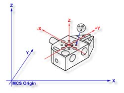
| figure 1, Datum target layout |
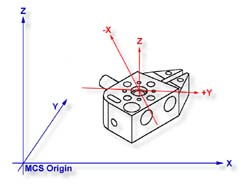
figure 2, Completed PCS |
Practice Steps
Step 1
Select Circle
<z>, if auto-direction is not activated,
you will be prompted for the Circle type: ID, OD, IR, or OR, choose ID. Capture the four
data points identified as A-ID/4, see figure 1.
Step 2
Select the Pivot Align
command, press < Ctrl + k
>. Note: Junior Users if you do not have the Advanced PCS and Stylus option, you will be prompted
whether to realign PCS 1 or cancel, select < Ok >. The current PCS will realign
through the last feature.
Summary
In this exercise, we choose to realign by pivoting though a feature that lies at 45°
to the current PCS. This can cause unexpected results during part program runs. For
example, if the feature was at 44.99° from the X axis during self teach it would realign
by rotating counter-clockwise 44.99° about the Z axis. However, if during self-teach the
feature was 45.01° the realignment would take place by rotating 44.99° clockwise causing
a 90° shift in the expected PCS.
We recommend that caution should be taken where unexpected results can occur as is the
case of any 45° rotations or pivots.
Related Procedures:
Go to PCS Examples:
prev
1
2
3
4
5
6
7
8
9 10
11
12
next
Pivot Align,
Circle
|
| |
|
|


