Rotate
Introduction
In this exercise we will take an existing part coordinate system and rotate it about an
axis by a nominal value. The rotate command can be perform only about one PCS axis at a
time. If you require to perform compound rotations, the rotate command will be repeated.
As you must have a complete coordinate system defined, please setup your part described in
PCS Exercise 2.
 |
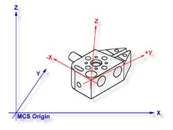 |
| figure 1, Established PCS |
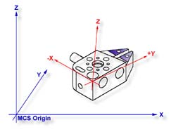
figure 2, Rotated PCS |
Practice Steps
Step 1
Select the Rotate
command, press <shift + : >.
When you select this command, a Rotate PCS Axis dialog will prompt you to enter a nominal
value for a axis, see figure 3.11c. Rotations can only be applied to one axis at a time,
therefore this rotation tool will ensure you enter only one value prior to accepting the
nominal value. For this exercise, enter -5 in the X axis control and press the
< Accept
> button.
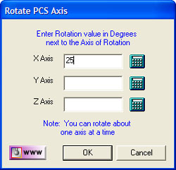 |
| figure 3, Rotate Dialog |
A new PCS will be established, or in the case of base Junior, a translation of the
current PCS takes place.
Summary
When we rotated the PCS -5° around the X axis, our resulting PCS should be parallel to
the top surface of the tapered plane as shown in figure 4.
 |
| figure 4, 5° tapered plane on GeoWidget |
To verify that we performed the rotation correct, select a -Z Point <2> feature
and probe the top surface of the 5° plane located on the tapered end of the GeoWidget. We
should see a -Z point value at .018 ± .005.
Related Procedures:
Go to PCS Examples:
prev
1
2
3
4
5
6
7
8
9
10
11 12
PCS Rotate
|


