Plane - Intersect Lines - Bisect Points - Circle
Introduction
In this exercise we will combine two constructed
features to create the secondary datum. These constructed features are derived from two
lines intersected and two 2D points bisected. The following example assumes the part is
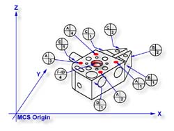
placed on your CMM where the cylinder of the GeoWidget is pointing in the -X direction.
 |
 |
| figure 1, Datum target layout |
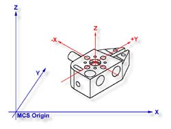
figure 2, Completed PCS |
Practice Steps
Step 1
Request a -Z plane
<b>, if auto-direction is not
activated, you will be prompted for the probing direction which you should select as -Z.
You will then be prompted to "Measure -Z Plane", (if auto-direction is active
"Measure Auto-Dir Plane"). Capture points A-1, A-2, A-3 and A-4 as shown in
figure 1.
Step 2
Select Orient
<j>. The orient command will create the
primary datum on the axis that is most normal to the machine coordinate system. In your
PCS Setup Guide, the Z Axis will be signed off.
Step 3
Select Origin
<l>. This will establish the Z origin
which is determined by the normal direction of the -Z plane.
Step 4
Request a Line feature
<m>, You will then be prompted
to select the probing direction, enter -X (if auto-direction is not active). The prompt
will update to display "Measure -X Line" (or "Measure Auto-Dir Line").
Capture points B-1 and B-2. When the points have been captured, you will be asked which
projection plane to use, select XY. A secondary request may be made to determine the
pierce axis, select X, see
Measured Features→Line for more information.
Step 5
Clear the current mode by pressing the < Esc > key. Request a Line feature
<m>, You will then be prompted to select the probing direction, enter +X (if
auto-direction is not active). The prompt will update to display "Measure +X
Line" (or "Measure Auto-Dir Line"). Capture points C-1 and C-2. When the
points have been captured, you will be asked which projection plane to use, select XY.
Step 6
Select the Intersect <d> command. This command will take the two projected lines
and solve for the intersect between them. The result will be a 2D XY point.
Step 7
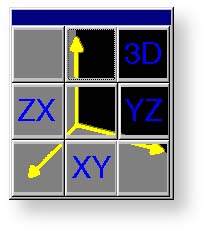 |
| figure 3, Select PCS Base Plane |
Select a 2D XY Point
<5 + 2>. The selection of
a 2D point requires two commands. The first command is activated by pressing the
< 5
> key, 2D and 3D point selection, which will then prompt which current base plane you
will project into, see figure 3.
After the selection has been completed, Geomet will prompt you to "Measure XY
Point". Capture points D-1 and E-1.
Step 8
Select the Bisect <a> command. This command will take the two projected XY points
and solve for the bisect between them resulting in a 2D XY point.
Step 9
Select in the report display feature number 7 by left-clicking on it (2D point formed
by the intersect command). Right-click your mouse and select from the popup menu,
<Recall Feature>. This will recall the feature and create new feature number 11.
Alternatively you can recall a feature by pressing the Recall Feature <h> command
from the keyboard. In the control labeled "<- Enter Feature No. to Recall" ,
enter 7 and press the <Ok> button or the <Enter> key on the keyboard.
Step 10
Select Align
<k>. Your ICS will update to include the
secondary datum which is derived from the recalled 2D XY point and the previous 2D XY
point created from the bisect.
Step 11
Select Circle
<z>, if auto-direction is not activated,
you will be prompted for the Circle type: ID, OD, IR, or OR, choose ID. Capture the four
data points identified as F-ID/4, see figure 1.
Step 12
Select Origin
<l>. the Circle, which is 2D, provide two
directions when establishing an origin. In our example, the circle can be used for the X
and/or the Y direction. The origin command will prompt you whether to use the X and then
the Y. For our example you should answer Yes to both requests. Upon completion, you will
have established PCS 1, see figure 2.
Final Inspection Report
In this exercise we had combined features to create constructed features which are then
used to create part coordinate system components. In part production we will find numerous
cases where one or more part coordinate system datums are symmetry lines or points where
no features exist.
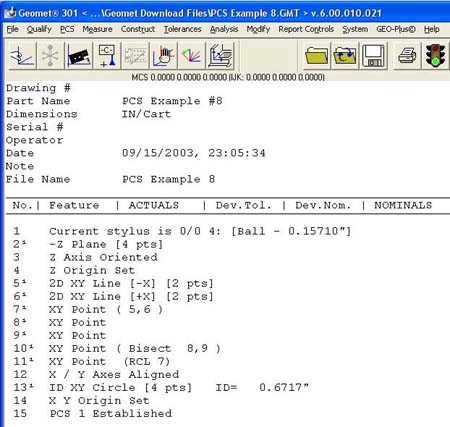 |
| figure 4, Final Inspection Report |
When performing constructions in a ICS, it is important to remember the established
projection base planes that are valid. For example, in this exercise it would not have
produced acceptable results if we established 2 ZX point, one each on the top and bottom
surfaces of the GeoWidget and then performing the bisect. The resulting 2D point would be
projected into the alignment of the machine coordinate system and therefore would not
represent a valid point feature for the part coordinate system.
Related Procedures:
Download PCS Example #8 (.zip)
Go to PCS Examples:
prev
1
2
3
4
5
6
7 8
9
10
11
12
next
Orient,
Align,
Origin,
Plane,
Line,
Circle,
2D Point
|


