Step 1
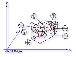
Request a -Z plane
<b>, if auto-direction is not
activated, you will be prompted for the probing direction which you should select as -Z.
You will then be prompted to "Measure -Z Plane", (if auto-direction is active
"Measure Auto-Dir Plane"). Capture points A-1, A-2, A-3 and A-4 as shown in
figure 1.
Step 2
Select Orient
<j>. The orient command will create the
primary datum on the axis that is most normal to the machine coordinate system. For
example, if the plane used by orient was determined to be a XY plane then the normal will
most closely align with the Z axis. In your PCS Setup Guide, the Z Axis will be signed
off.
Step 3
Select Origin <l>. This will establish the Z origin which is determined by the
normal direction of the -Z plane.
Step 4
Request a Line feature <m>, You will then be prompted
to select the probing direction, enter -X (if auto-direction is not active). The prompt
will update to display "Measure -X Line" (or "Measure Auto-Dir Line").
Capture points B-1 and B-2. When the points have been captured, you will be asked which
projection plane to use, select XY. A secondary request may be made to determine the
pierce axis, select X, see
Measured Features - Line for explanations.
Step 5
Select Align
<k>. Your ICS will update to include the
secondary datum which is derived from the XY line feature.
Step 6
Select Origin
<l>.
This will establish the X origin which is determined by the reported direction of the XY
Line.
Step 7
Request a +Y Point feature <9>, You will then be
prompted to "Measure +Y Point". Capture point C-1.
Step 8
Select Origin
<l>. This will establish the Y origin and
complete the ICS to a full part coordinate system. The PCS Setup Guide will disappear and
you are now ready to take feature measurements.
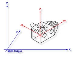
The Plane-Line-Point combination of features are
commonly used for most machined parts to set the part coordinate system, see figure 2.
|
 |
|
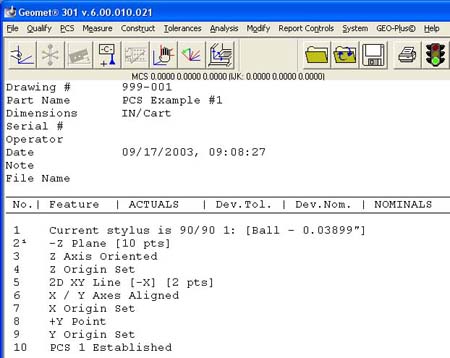
figure 3, Final Inspection Report |
It is important to remember that the features in these exercises are utilizing minimum
data points to achieve a complete PCS. There are several factors that can negatively
effect the quality of your data points. These include probing speed and distance between
data points just to name two.
In the case of the alignment, we used two points to calculate the line. The
repeatability of the electronic trigger probe can be as much as .00014" with a
standard 20 mm extension. If the two points for the line were taken 0.500" apart, the
possibility exists of .00028" error per inch, when applied to the PCS effects all
features being measured. It is therefore important that you select the most stable features
to establish your PCS and balance the number of data points to help reduce inherent CMM
and operator errors.