Step 1
Select Cylinder
<c>, if auto-direction is not
activated, you will be prompted for the cylinder type ID, OD, IR, or OR, choose ID.
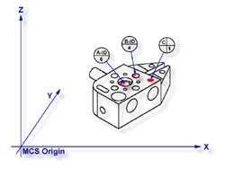
Capture the six data points identified as A-ID/6, see figure 1.
Step 2
Select Orient
<j>. The orient command will create the
primary datum on the axis of the cylinder that is most parallel to the machine coordinate
system. In your PCS Setup Guide, the Z Axis will be signed off.
Step 3
Select Origin
<l>. This will establish the origin
reported as the pierce point of the cylinder. In this example, the cylinder pierces the XY
base plane and the origin command will prompt you whether or not to set the origin on the
X and/or the Y. Answer yes to establish the XY origin.
Step 4
Select Circle
<z>, if auto-direction is not activated,
you will be prompted for the Circle type ID, OD, IR, or OR, choose ID. Capture the four
data points identified as B-ID/4, see figure 1.
Step 5
Select Align
<k>. Your ICS will update to include the
secondary datum which is derived from the XY circle and the previous XY pierce point from
the cylinder.
Step 6
Select -Z Point
<2>. The final component missing for
your complete PCS is the Z origin. You will then be prompted to "Measure -Z
Point". Capture point C-1.
When using a through bore as the primary datum, we must be careful that the data point
spread is sufficient to allow for a stable feature.
 |
|
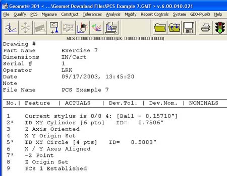
figure 3, Final Inspection Report |
In this example we would place an
extension on the stylus to allow for a greater reach into the cylinder.