Coordinate System Secondary Datum
Command Activation
| k |
PCS→Align |
 |
| Keyboard |
Main Menu |
Toolbar |
Definition
Align acts on the last measured or recalled 3D or 2D directed feature or pair of
non-directed features which could serve to create a 2D or a 3D directed feature. For
example, a pair of 1D co-directional points, pairs of coplanar 2D points, or pairs of 3D
points. The Align command will see through transparent operations such as other PCS
formation commands, distance, angle commands, etc. Align establishes the directions of the
secondary and tertiary PCS axes, with the selection of X, Y and Z determined by the MCS X,
Y or Z axis to which the directed feature axis is most parallel. Geomet will validate the
last feature(s) to determine whether they are capable of providing a secondary datum,
see
table 1.
 |
| figure 1, Select PCS Base Plane for Alignment |
Align, when executed in an ICS directly after the orient has been established, makes an
automatic choice of the alignment axis. For example, if the orient command resulted in
establishing the Z axis, then the Align command will rotate about the Z to establish the
secondary datum.
When the Align command is executed in an established PCS, the resulting operation
creates a new PCS by aligning to the requested feature. The Align command will determine
the alignment axis when a pair of co-directional 1D points or coplanar 2D features are
used. When using a pair of 3D features or a 3D axial feature, Geomet will prompt for the
PCS base plane to align in, see figure 1.
Feature Validation Tables
| |
1D Point |
2D Point |
3D Point |
Circle |
Ellipse |
Line |
Plane |
Sphere |
Cylinder |
Cone* |
| Align |
|
|
|
|
X,2 |
X,1 |
X |
|
1 |
1 |
|
Notes:
1 - 3D Lines, Cylinders, Cones the axis is projected into a specified PCS base
plane, then aligned.
2 - Utilizes the Major or Minor Axis of the Ellipse. |
| table 1, Align based on a single
feature |
| |
1D Point |
2D Point |
3D Point |
Circle |
Ellipse |
Line |
Plane |
Sphere |
Cylinder |
Cone |
| 1D Point |
X |
X |
X |
X |
|
|
|
X |
1 |
1 |
| 2D Point |
X |
X |
X |
X |
X |
|
|
X |
1 |
1 |
| 3D Point |
X |
X |
X |
X |
X |
|
|
X |
1 |
1 |
| Circle |
|
X |
X |
X |
X |
|
|
X |
1 |
1 |
|
Ellipse |
|
X |
X |
X |
X |
|
|
X |
1 |
1 |
| Line |
|
|
|
|
|
|
|
|
|
|
| Plane |
|
|
|
|
|
|
|
|
|
|
| Sphere |
X |
X |
X |
X |
X |
|
|
X |
1 |
1 |
| Cylinder |
X |
X |
X |
X |
X |
|
|
X |
1 |
1 |
| Cone |
X |
X |
X |
X |
X |
|
|
X |
1 |
1 |
NOTES:
1 - Based on projected 2D Pierce Point, not the axis.
2 - Oval Slot / Slot Web / 4 Point Intersect are treated similar to a 2D Point |
| table 2, Align using 2 feature
combinations |
Special Considerations
Care should be observed to select a feature that provides a well defined
alignment. The feature should be sufficient in length to prevent adding
errors into the final results. For example if a line is used that is 1"00 in
length and the inspected part is 10"00 in overall length, then we would have
a 1:10 ratio. If the misalignment of the feature to part was 0.0001", then
at 10"00 it would be 0.001" in errors, see
Technical Note #2 for some common errors in a CMM.
Using 3D features, such as a Cylinder should be used with care. Using the
Cylinder as an example, let's first review how a Cylinder is projected into
the current PCS Base Planes.
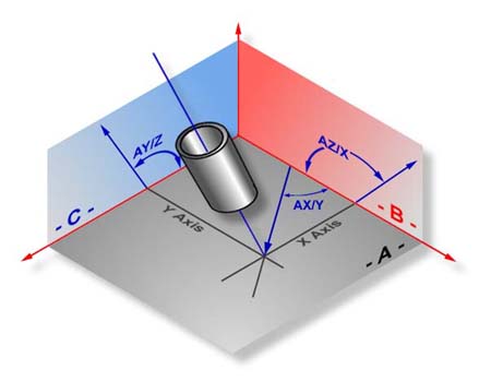 |
| figure 2, Cylinder Projection |
In figure 2, the Cylinder is shown piercing the XY base plane of the PCS.
If the orientation plane was also the XY base plane, then any alignment
would take place along the angle AX/Y. The length of AX/Y is the protection
of the end points of the Cylinder Axis into the base plane XY. If the
Cylinder axis was parallel to the normal vector of the orient vector (plane
vector) then the length between the projected endpoints would be 0.00"! and
no alignment would be allowed.
In figure 2, the cylinder could be used as an alignment feature only if
the Orient feature was the YZ or ZX plane.
|


