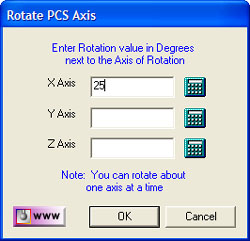
In the Rotate PCS Dialog, see figure 1, we show a request to rotate the
current PCS 25° around the X axis. To ensure only one axis of rotation, any entry in Y or
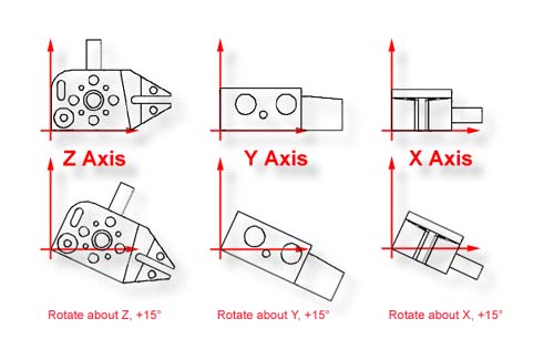
Z, would result in clearing the entered value in X. In the examples shown in figure 2, a
rotation is applied to each axis with its corresponding change in relationship to the
sample part.
A Rotate PCS feature once applied creates a new Part Coordinate System. To edit
the existing rotation value when there are features using the rotated PCS is allowed, but
a warning is provided to rebuild all coordinate systems by running the program from the
beginning.
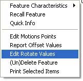 |
| figure 3, Sub Menu |
To edit the existing rotation feature, highlight that feature and bring up the sub menu
by right clicking, see figure 3. The ability to edit a translated feature is only
available when the translate feature has absolute entered values, not values derived from
the last feature option.
Enter the new rotate value in the space provided, see figure 1, and
press the <Ok> button. Geomet will display a warning that the features after
translation step will no longer have valid positional data, see figure 4.
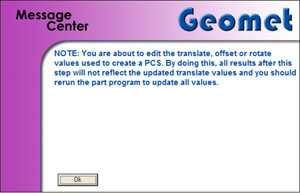 |
| figure 4, Warning Statement |
At this time, save the part inspection file and run the file to rebuild the Part
Coordinate Changes.