|
|
Coordinate System Secondary Datum
Command Activation
| shift + K |
PCS→Offset Align |
|
| Keyboard |
Main Menu |
Toolbar |
Definition
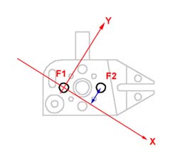 |
| figure 1, Offset Align Example |
Offset align acts exclusively on the last measured or recalled pair of coplanar 2D
features. Offset align requires that you are in an established PCS. Geomet will validate
the last two features to determine if they are compatible for the Offset Align command.
The offset align command will establish a new PCS by performing a re-alignment of the
current PCS.
|
Step 1
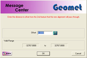 |
| figure 2, Enter Value for Offset Align |
Establishing the offset align requires two co-planar 2D features with are measured or
recalled, see table 1 for valid combinations. In the example shown in figure 1 we
will use two XY circles identified as F1 and F2. The order in which they are reported in
the part program will determine the re-alignment order. In this example F2 was measured or
recalled after F1. To perform the offset align, press the keys
<shift + K > and the Enter Values control will appear, see figure 2.
Enter the sign and magnitude of the nominal offset applied to feature F2, relative to
an imaginary axis through the second feature, F1. In figure 1, the offset axis passes
through F1 and is created -0.50" from F2. Should you want the Offset Align to be
created above F2, you would enter +0.50" It is not mandatory for the first feature,
F1, to be on a PCS axis, or a PCS component.
Feature Validation Table
| |
1D Point |
2D Point |
3D Point |
Circle |
Ellipse |
Line |
Plane |
Sphere |
Cylinder |
Cone |
| 1D Point |
|
|
|
|
|
|
|
|
|
|
| 2D Point |
|
X |
|
X |
X |
|
|
|
X |
X |
| 3D Point |
|
|
|
|
|
|
|
|
|
|
| Circle |
|
X |
|
X |
X |
|
|
|
X |
X |
|
Ellipse |
|
X |
|
X |
X |
|
|
|
X |
X |
| Line |
|
|
|
|
|
|
|
|
|
|
| Plane |
|
|
|
|
|
|
|
|
|
|
| Sphere |
|
|
|
|
|
|
|
|
|
|
| Cylinder |
|
1 |
|
1 |
|
|
|
|
1 |
1 |
| Cone |
|
1 |
|
1 |
|
|
|
|
1 |
1 |
NOTES:
1 - Based on projected 2D Pierce Point, not the axis. |
| table 1, Offset Align using 2
feature combinations |
An Offset Alignment procedure once applied creates a new Part Coordinate System. To
edit the existing offset value when there are features using the PCS created by an offset
align is allowed, but a warning is provided to rebuild all coordinate systems by running
the program from the beginning.
To edit the existing offset value, highlight that feature and bring up the sub menu by
right clicking, see figure 3. The ability to edit a translated feature is only
available when the translate feature has absolute entered values, not values derived from
the last feature option.
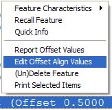 |
figure 3,
Sub Menu |
|
|
figure 4,
Offset Align Edit Dialog |
Enter the new offset value in the space provided and press the <Ok> button.
Geomet will display a warning that the features after translation step will no longer have
valid positional data, see figure 5.
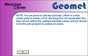 |
| figure 5, Warning Statement |
At this time, save the part inspection file and run the file to rebuild the Part
Coordinate Changes.
|
| |
|
|


