Command Activation
| Ctrl + 5 |
Measure→Auto Features→Point Generator |
|
| Keyboard |
Main Menu |
Toolbar |
Definition
The Point Generator feature
builds and tolerances 1D, 2D and 3D point features. This allows building of
offline features when not connected to a coordinate measuring machine or
when the
production part is not available. The Point Generator also provides tools
to build all motion path and can execute on demand the measuring of the new
point.
The Circle Generator also provides a step and repeat
function to create rows and columns of data points for capturing multiple
point features.
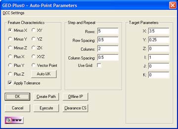 |
| figure 1,
The Point Generator |
Using the Point Generator to Create a New Feature
To create a new feature, activate the generator by
pressing <Ctrl + 5> simultaneously or by selecting [Measure→Auto Features→Point Generator] from the drop down menu. NOTE: the key press "5" is
located on the number pad, not the row of numbers over the top of the
keyboard.
Step 1 - Feature Characteristics
Complete the selections in the Feature Characteristics
Group
- Choose the Point type:
1D Points,
2D Points,
3D Points
- Select Apply Tolerance if required.
When selecting a 1D Point type (-X, -Y, -Z, +X, +Y or
+Z), a command button labeled <Auto IJK> will become available. This command
when selected, will apply standard default values in the I, J and K controls
located in the Target Parameters group. The ability to perform Step and
Repeat capabilities are available only when 1D Point type has been selected.
Step 2 - Step and Repeat
The Step and Repeat function is available when 1D
Point type has been selected.
Under The Step and Repeat group you have the option to
specify rows and columns of data points that will be orthogonal to the
current Part Coordinate System. The number of data points and spacing
between the rows and columns are separately controlled.
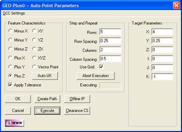 |
| figure 2,
Step and Repeat Activated |
To activate the Step and Repeat tool, place a check
next to Use Grid: . Additional information will appear which allow you to
abort the execution when using on a DCC style CMM.
Enter the parameters for the row and column count and
spacing. The values you enter for spacing is sign sensitive. These spacing
values are applied against the XYZ position entered in Target Parameters
group which is considered the starting point of the grid.
The grid is assumed to be parallel to a PCS base plane
and does not perform any contour walking capabilities. Those commands are
better suited by the Scanning Tools within Geomet. For example: a -Z Point
will expect a constant Z through the execution of the grid.
Step 3 - Target Parameters
Complete the values required in the Parameters Group
- Enter the XYZ contact point location
- Enter the IJK approach vector
NOTE: The IJK approach vector
is defined as a direct line to the contact point that
is perpendicular to the surface. Using the surface plate of your CMM as an
example, we know the IJK surface vector is I=0.0, J=0.0, K=1.0. Therefore
when we specify a -Z 1D Point, the surface normal would be I=0.0, J=0.0,
K=1.0. If we select the <Auto IJK> command button, the IJK controls will
populate with these values.
Some IJK values will be difficult to calculate when
the surface is not parallel to a PCS Axis. If your inspection part has a CAD
drawing associated to it, most CAD programs can easily provide the IJK
values.
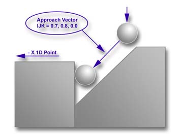 |
| figure 3,
IJK Approach
Vector |
It is not necessary to always approach the contact
point along the IJK approach vector. When you teach an inspection program
you generally do not control the CMM with such a high degree of motion
accuracy. Therefore you should enter an IJK that allows direct line-of-sight
approach to the contact point. In figure 3, we have a condition where the
surface we need to measure has a restriction on approach. We must account
for this by entering a IJK that provides a safe line-of-site approach to the
contact point.
Our inspection requires that a -X 1D Point be used to
contact the step. Under normal conditions, we would enter an IJK value of
1.0, 0.0, 0.0. However to clear the restricting surface, we used the
approach vector 0.7, 0.8, 0.0. The Stand-Off Point would be created along
that approach line.
To get a simple understanding, if we stood on the
contact point, we would look at a line from the contact point alongside the
restricting surface. In this example, we moved 0.7" along the X-Axis and
simultaneously, move 0.8" along the Y-Axis.
Vector Point
When the Point Type selected is Vector Point,
additional parameters will appear in the Target Parameters group. These
include Probe Deviation, Plus and Minus Deviation, see figure 4.
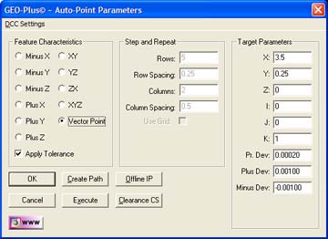 |
| figure 4,
Vector Point
Target Parameters |
Vector Points are executed one-at-a-time. If you require
a grid of Vector Points we suggest using the Vector Point Generator
described
here.
A good description of the deviation fields and general information regarding
Vector Points can be found
here.
A detailed explanation regarding Vector Point can be found in our technical
notes section and titled:
Curved Surface Measurement with Vector Point
Motion Path Adjustments
There are several tools available to build motion
paths to ensure clear motion without collision into the inspection part, or
clamps and other obstacles. These include Clearance Coordinate Systems,
offline IPs and Automatic IPs.
Clearance Coordinate Systems
A complete description on Clearance Coordinate Systems
can be found here.
Creating offline IPs and Automatic IPs
Once the Clearance Coordinate System has been
establish and set active, Offline IPs can be generated to build a motion
path for safe CMM travel,
see Offline IPs.
Execute
This command acts upon the values displayed in the
Point Generator and instructs the CMM to perform the inspection.
When executing a row / column grid, the CMM will start
at the first point as defined in the Target Parameters group and move in
column number 1 until reaching the required number of points. The CMM will
then move to column number 2 (if required) and reverse direction to the
bottom of column number 2. The CMM will continue this operation until all
data points have been captured.
|


