Introduction
The Clearance CS Manager is a tool that allows you to build clearance coordinate systems around
your part where you can move your probe without interfering with the part preventing accidental probe trips. The Clearance CS tool is most often used when creating auto features
such as lines and circles.
There can be any number of Clearance CSs created, but only 1 can be active at any time.
The Clearance CS contains 3 base planes and an origin. They have the same composition as any
Part Coordinate System.
Creating a Clearance CS
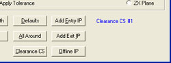
To start the Clearance CS tool, click on the <Clearance CS> button from any
auto-feature tool, see figure 1, or from the PCS drop down menu,
[PCS→Build Clearance CS].
 |
 |
| figure 1, CCS Tools within a Feature Generator |
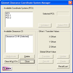
figure 2, CCS Setup Tool |
In figure 2, we have two display lists, one identified as Available
Coordinate Systems (PCS) the second Available Clearance Plane CS.
The first list as defined shows all PCSs in your current inspection. The
second list shows all created Clearance CSs already associated with the inspection.
 |
 |
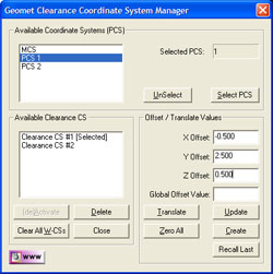
| figure 3, Selecting an
Existing PCS |
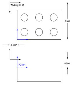
figure 4, Clearance CS to PCS Relationship |
To create a Clearance CS, start by highlighting
a PCS in the available list, see figure 3 where PCS #1 is highlighted.
Click the <Select PCS> button or double click on the PCS name in the list. Control
will pass to the "Offset / Translate Values" group allowing you to enter XYZ
offset values. These values should be carefully understood, as they will directly affect
the motion of your system. The 1-2-3 block example in figure 4 , shows that the
Part Coordinate
System is established on the top surface and lower left corner.
We will enter offset values of:
- X Offset: -0.500
- Y Offset: 2.500
- Z Offset: 0.500
After entering the values, press the <Create> button and a new Clearance CS will
appear in the list with the next available number. As shown in figure 4, the Clearance CS
has its origin outside the part creating three planes that will allow motion within those
planes that will not intrude into the part.
You can create as many Clearance CSs that are required to provide zone transition planes
around your part and any fixtures being used.
Translate an Existing Clearance CS
Translate allows you to quickly take an existing Clearance CS and create a new Clearance CS based on XYZ Offset values. To illustrate, we will
take Clearance CS #1 and create a second Clearance CS 3.000" in the –Y direction.
Start by highlighting the name "Clearance CS #1", the current values will
display in the Offset / Translate Group. Edit the XYZ translation values to:
- X Offset: -0.000
- Y Offset: -3.000
- Z Offset: 0.000
Press the <Translate> button and a new Clearance CS is created and entered into the
available list.
Update an Existing Clearance CS
This feature allows you to update the current offset
values for an existing Clearance CS. In some cases it may be required to extend an offset
for better motion path generation. To update an existing Clearance CS, highlight that Clearance CS in the list and when the current entered values are displayed in the Offset /
Translate Group, you can then edit them. Make the changes to the Clearance CS by pressing
The <Update> button.
NOTE: Any feature that currently uses the Clearance CS being updated will have all motion
relating to the Clearance CS updated automatically.
Deleting a Clearance CS
Deleting a Clearance CS will remove all references to the clearance planes defined in the
selected Clearance CS. To delete, highlight the name in the Available Clearance Plane
CS list. Click on the button <Delete> and it will be removed permanently
from the inspection program.
NOTE: Any features that refer to the deleted Clearance CS must be reviewed and corrected
manually.
Clear All Existing Clearance CSs
This feature will remove all Clearance CSs from you part program. Caution should be taken
when using this feature. If your part program has any Auto-IPs, they will lose reference
to the Clearance CS and motion behavior can be greatly affected.
NOTE: Unlike Part Coordinate Systems, Clearance CSs contain relative offset values based
on a recalculated PCS. Every time a part inspection is performed, any PCSs are rebuilt
based on current features. Clearance CS are then build against the assigned PCS and
therefore it is considered dynamic during the part inspection.
Activating a Clearance CS
Activating a Clearance CS will allow all other editing tools to use the clearance planes
defined in the Clearance CS. To set it active, highlight the name in the Available Clearance Plane CS list.
To change its status, click on the button <(de)Activate> .
|


