Command Activation
| Ctrl +
b |
Measure→Auto Features→Plane Generator |
|
| Keyboard |
Main Menu |
Toolbar |
Definition
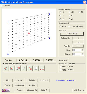
The Plane Generator tool builds and tolerances plane
features. This allows building of offline features when not connected to a
coordinate measuring machine or when the production part is not available.
The Plane Generator also provides tools to build all motion paths that can
be executed on demand for the measuring of the new plane.
The Plane Generator tool has two functions. The first
is to create a new feature. The second provides access to editing an
existing feature whether created by the generator or manually taught.
|
|
| figure 1, Plane Generator |
NOTE: When editing a plane feature that was not created with the Plane
Generator care must be taken to account for IPs that may be inserted between
the first and last Stand Off. The Generator does not retain those IPs.
Using the Point Generator to Create a New Feature
To create a new feature, activate the generator and follow these steps:
Step 1 - Defining the boundary of the plane
Complete the selections in the Parameters Group
- Select the probing direction.
- Enter the four XYZ corner end points.
- Select the number of rows and columns
Step 2 - Feature Characteristics
Complete the values required in the Feature
Characteristics Group
- Reverse IJK if required.
- Select the reported PCS Pierce Axis.
Step 3 – Exclusion Zones
Exclusion Zones are added to the plane to account for
portions of the surface where a hole or slot may cut through. Data points
defined by the row and column positions may fall within these exclusion
features. The Exclusion Zones removes those data points from the final
motion map.
Step 4 - Motion Path Adjustments
There are several tools available to build motion
paths to ensure clear motion without collision into the inspection part,
clamps and other obstacles. These include Clearance Coordinate Systems,
offline IPs and Automatic IPs.
Creating Offline IPs and Automatic IPs
Once the Clearance Coordinate System has been
established and set active, Offline IPs can be generated to build a motion
path for safe CMM travel,
see Offline IP Generator.
Special Interim Point Commands
In most applications, the use of the command <Add
Entry IP> and <Add Exit IP> will ensure safe transition for your CMM into
and out of features. The use of these commands requires that a Clearance CS
is currently set active.
The Add Entry IP command will calculate an IP directly
over the feature in the normal base plane. For example, in the XY line
example, the first Standoff Point is extracted and projected into the XY
Base plane of the active Clearance CS. The motion will start directly over
the line and plunge to the first SO safely.
The Add Exit IP command creates a similar IP to Add
Entry IP except it will use the last SO as its reference. The combination of
these two commands results in the CMM moving directly over the first SO,
perform the measurement and exit the line safely.
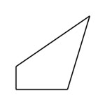
Defining the Corner End Points
The Plane Generator defines the boundary of planes as
having four straight sides, shown here are some examples:
 |
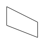 |
figure 2,
Acceptable |
figure 2,
Acceptable |
 |
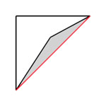 |
figure 2,
Acceptable |
figure 2,
Not Acceptable |
The shape of the enclosed area can be a wide variety,
however there is one rule the shape must follow. That example can be seen in
the right image where one end point is inside a straight line drawn between
its adjoining corners. The Plane Generator will test for this condition and
prompt you to correct it.
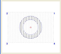
Entering End Points
|
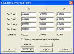 |
| figure 6, Corner Endpoint Tool |
Press the button <Set End Points> to launch the
Boundary Corner Endpoints dialog. The simplest method is to enter the XYZ
values for each corner directly into the cells.
<Capture>
If you have a CMM attached and your part is available
you can use the <Capture> function. When you press <Capture> Geomet will
prompt you to take 4 data points. Capture the 4 data points around the
boundary of the surface where you want your plane measured. As you make
contact, the data points XYZ position will update in the dialog.
These Points are entered as surface points
When checked, the entered XYZ corner points are on the
surface of the plane. This is important when working off line of the CMM.
When you capture the end points using the CMM, the XYZ values are not
compensated for the probe direction. The information for the plane normal
has not yet been developed.
<Recall Last>
The Plane Generator writes the 4 end points out to the
registry for recall at a future time.
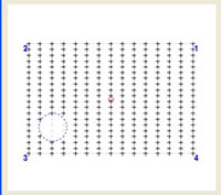
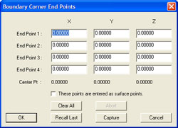
Building the Motion Map Example
|
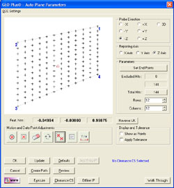 |
| figure 7, Endpoints Set |
In our example, we will use a 1-2-3 Block with the
standard 6 holes through the part. The PCS is defined on the part and its
origin is located on the lower left corner.
The four end points were manually entered and are:
| |
X |
Y |
Z |
|
Endpoint 1 |
0.000 |
0.000 |
0.000 |
|
Endpoint 2 |
3.000 |
0.000 |
0.000 |
|
Endpoint 3 |
3.000 |
2.000 |
0.000 |
|
Endpoint 4 |
0.000 |
2.000 |
0.000 |
In the Boundary Corner End Points dialog, we placed a
check on the “These Points are entered as surface points” option. When this
was finished, we pressed the <Ok> button. The graphic area will now update
showing the data point spread.
Rows are set at 20 and columns are set at 15. The
Plane Generator will display the data point distribution based on this data.
Please note the calculated IJK values are:
|
I |
J |
K |
|
0.0000 |
0.0000 |
-1.0000 |
This indicates the plane vector normal is pointing downward from the
surface of the part. Our plane has a real vector normal of:
|
I |
J |
K |
|
0.0000 |
0.0000 |
1.0000 |
To correct this, press the <Reverse IJK> button. It is important that the
vector direction is correct when building the motion path. With the vector
normal now pointing “up” the probe path will be generated above the part.
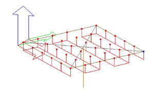 |
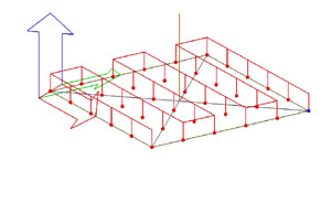 |
figure 8,
Incorrect IJK, Probing from the bottom |
figure 9,
Correct IJK, Probing from the top |
Data Point Edge Clearance
 |
|
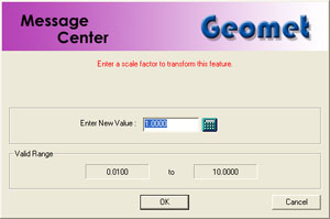
figure 11, Enter Scale Value |
|
|
 In our example we are using a 1-2-3 block and our endpoints that define
the plane boundary are the real edges of the part. This is not a good
practice as our CMM will move to the exact edge and capture data points.
Since our stylus is a sphere, we will get questionable data points that will
result in an erroneous solved plane. In our example we are using a 1-2-3 block and our endpoints that define
the plane boundary are the real edges of the part. This is not a good
practice as our CMM will move to the exact edge and capture data points.
Since our stylus is a sphere, we will get questionable data points that will
result in an erroneous solved plane.
To remedy this condition we could have entered corner points that are
inside the physical boundaries, or we can scale our endpoints using the
Scale tool.
The value you enter in the Scale Dialog is a percentage of the total
boundary area.
| |
Original Entered Values |
Scaled Values |
| |
X |
Y |
Z |
X |
Y |
Z |
|
Endpoint 1 |
0.0000 |
0.0000 |
0.0000 |
0.0750 |
0.0500 |
0.0000 |
|
Endpoint 2 |
3.0000 |
0.0000 |
0.0000 |
2.9250 |
0.0500 |
0.0000 |
|
Endpoint 3 |
3.0000 |
2.0000 |
0.0000 |
2.9250 |
1.9500 |
0.0000 |
|
Endpoint 4 |
0.0000 |
2.0000 |
0.0000 |
0.0750 |
1.9500 |
0.0000 |
With the scaling operation completed, we now have a safe distance between
the edge of the physical part and where the data points are captured.
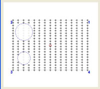
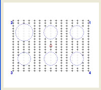
Exclusion Zones
To eliminate data points from the grid, the Plane Generator provides
three tools.
|
Exclusion Zone Tools |
 |
Radial Exclusion Zone defined by a center point and radius. All data
points that fall within this zone will be removed from the motion
map. The Radial Exclusion Zone is a fixed position that does not
scale. |
 |
Boundary Exclusion Zone is defined by 4 endpoints. All data points
that fall within this zone will be removed from the motion map. The
Boundary Exclusion Zone is a fixed position that does not scale. |
 |
This tool creates a small 0.05” radius Target Exclusion. The center
position of the zone is positioned with mouse. As you position over
a existing data point, an anchor shows, left click to set the zone. |
Radial Exclusion Zone
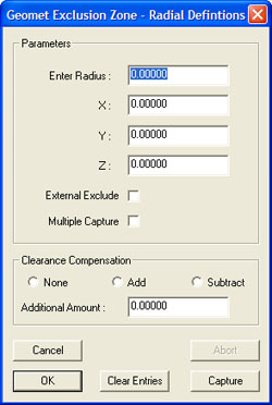 |
|
figure 12, Radial Definitions |
The
Radial Exclusion Zone is used to delete data points from the motion map
where a hole might exist on the surface that would interfere with measuring
of a plane. There are many options available in building Radial Exclusion
Zones.
Basic Radial Exclusion Zone
Using our 1-2-3 block example we have 6 holes, or areas where no data
points should be taken. Enter the XYZ center for the first hole:
|
X |
Y |
X |
|
0.5000 |
0.5000 |
0.0000 |
Now enter the radius of the hole, which is 0.250” and press <Ok>. The
example below shows the removal of data points for that one exclusion zone.
|