Introduction
The Offline IP Generator provides a simple tool to
create, edit and manage Interim Points within your motion map of a
feature. Through this tool you can designate absolute XYZ IP values, or
create dynamic automatic IPs.
Automatic IPs work with Clearance Coordinate
Systems. An automatic IP is calculated at the time of execution and is
not recorded in the motion map with XYZ values. For example, when
requesting an Z-Axis Automatic IP, the CMM will move from its current
location into the XY plane of the Clearance CS. The move will be
parallel to the Z-Axis of the Clearance CS.
The Offline IP tool manages the initial IPs before
the first Standoff Point (SO) in the feature's motion path. It is not
designed to create or edit IPs that are inserted after the first SO or
any IPs at the end of the feature after the last SO.
Creating a Offline Interim
Point
To start the Offline IP tool from inside a Auto Feature Generator, click on the <Offline
IP> button, see figure 1.
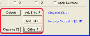 |
| figure 1, Start Offline IP from a Auto Feature Generator |
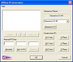 |
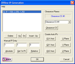
| figure 2, Offline IP Main Screen |
In figure 2, we show the Offline IP tool with
no data points in the display. Through the
Offline IP tool, we have access to building all necessary IPs required
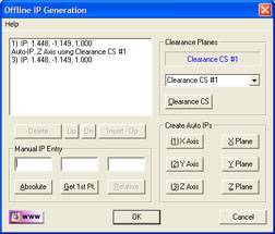
for safe CMM motion. In figure 3, we show two IPs have been inserted at
the start of the motion map. The first point is an automatic IP moving
into Clearance CS XY base plane with motion parallel to the Z-Axis. The
second IP is a calculated IP over the first SO of the measured featured.
All this has been done by just pressing the <Z Plane> button.
 |
| figure 3, Selecting an
Existing PCS |
Offline IP Tool Layout
The Offline IP Tool contains three groups of
controls, plus a display of IPs that are assigned. The first group
belongs to Manual creation of IPs. From this control, you can create
absolute position XYZ IPs, relative IPs and obtain the XYZ location of
the first SO in the feature.
The next group accesses the Clearance Coordinate
System tools. All the automatic IPs require that a Clearance CS is
selected. The <Clearance CS> button activates
the Clearance CS tool to create, edit and activate a Clearance CS.
The final group is called Create Auto IPs. There
are six buttons which create automatic IPs. The buttons label X, Y and Z
Axis, will create an automatic IP which moves parallel to the selected
Clearance CS axis into the base plane. The buttons labeled X, Y and Z
Plane creates two IPs, the first is an Automatic IP, the second is a
calculated IP over the measured feature.
Manual IP Entry
Within the Manual IP Entry group there are three
edit controls associated with the XYZ values associated with a IP and
three command buttons.
Absolute IPs
To create an IP where you enter the absolute XYZ
values, enter in the edit controls the desired values.
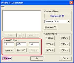 |
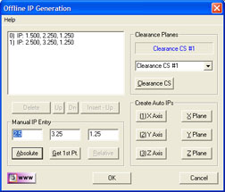
| figure 4, Entering Absolute IP Position |
In this example, we entered:
X = 1.5
Y = 2.25
Z = 1.25
To confirm and create the IP, Press the <Absolute> button. An entry of the newly created IP will be shown in the display
area, see figure 5.
Relative IPs
The Relative IP function, creates a new IP at an
offset XYZ distance from the highlighted IP in the list. Start by
selecting an IP in the display.
 |
 |
| figure 5, Entering a Relative IP Position |
figure 6, New Relative IP Position added |
As shown in figure 5, we have selected
the first IP. When the IP has been selected, the <Relative> button
becomes active. Enter an XYZ offset distance in the edit controls. We
show the example of entering:
X = 1
Y = 1
Z = 0
Complete the process by pressing the <Relative> button. A new IP is created that has a offset value of X=1.0, Y=1.0,
Z=0.0 to the selected IP, see figure 6.
Get 1st Point
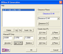 |
| figure 7, Obtain the 1st Standoff Point |
This command retrieves the first Standoff position
in the motion path. As shown in figure 7, the first Standoff Point is:
X = 3.6389
Y = 3.3750
Z = -1.2500
The XYZ location of the first Standoff Point is
helpful when you are creating a new IP. For example, if we are creating
an XY Circle, with a probing depth is identified by the Z value
(-1.2500). If we wanted an IP over the SO Point which will allow for
safe motion of the probe, we can change the Z value of the first point
to 0.5" and press the <Absolute> button. Now we have an IP directly over
the first SO Point. The probe will move to the point, then plunge into
the hole to commence measurement.
NOTE: The Get 1St Point command works with the
motion path already determined in the auto feature tool. In this example
we are using a 2D XY Circle. If you change the sweep start value, then
the first SO will change. When you change the sweep start value, you
should return to the Offline IP tool to confirm the IP originally
created is also updated.
Clearance Planes
This group provides a simple drop down control
which lists all the current Clearance CS systems in your inspection.
Choose the Clearance CS you want active before you start assigning
Automatic IPs.
If you find that a new Clearance CS must be
created, select the <Clearance CS> button.
Create Auto IPs
To create Auto IPs, you must first have a
Clearance CS active. If the six Auto IP generation buttons are disabled,
there are no Clearance CS active.
X Axis, Y Axis, Z Axis
These commands will create an Automatic IP based
on the axis selected. The X Axis command will create an IP that moves
from the current location into the Clearance CS YZ Base plane.
X Plane, Y Plane, Z Plane
These commands create two IPs in your motion path.
If you press the Z Plane command, the first IP created is an Automatic
IP that moves from the current point parallel to the Z Axis of the
Clearance CS into the XY Base plane.
The second IP create is the entry IP of your
current feature. It is calculated by taking the first SO in the motion
path and projecting that into the Clearance CS XY Base plane. In most
applications, this is all that is needed to move safely from one
location to the start of the feature.
For example, if measuring two XY circles, to move
from circle number 1 to circle number 2, we would select the Z Plane
command in the Offline IP tool. Upon completion of measuring circle
number 1, the probe is at the probe depth below the surface of the part.
The Z Plane command will first extract the probe in a pure +Z
direction into the XY Base plane of the defined Clearance CS, then
transition in the same XY Base plane until it is over the first point of
the second feature. From this point, the probe can now plunge into the
second circle to commence measuring.
Display List Controls
The display list has controls identified as <Delete>, <Up>, <Dn> and <Insert - Up>. These allow you to control and
position the IPs as needed.
Delete
Allows you to delete from the list the current
selected IP.
Up, Dn
These commands move the selected IP Up and Down in
the list.
Insert - Up
This command acts similar to the creating an IP
using the Absolute command. However, unlike the Absolute command which
always appends a new point, the <Insert - Up> command inserts a new
absolute IP in the same location as the selected IP and move all other IPs down.
|


