|
Command Activation
| Ctrl +
c |
Measure→Auto Features→Cylinder Generator |
|
| Keyboard |
Main Menu |
Toolbar |
Definition
The Cylinder Generator will build and tolerance Cylinder features. This
allows building of offline features when not connected to a coordinate
measuring machine or when the production part is not available. The Cylinder
Generator also builds all motion paths and can execute on demand the
measuring of the new cylinder.
The Cylinder Generator provides complete access to size, location, start
/ stop angles and motion path generators required to measure the feature.
The tool has two functions. The first is to create a new feature. The second
provides access to editing an existing feature whether created by the
generator or manually taught.
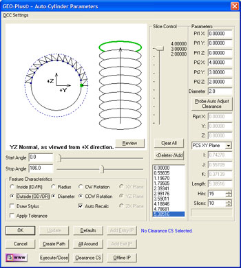 |
| figure 1,
The Cylinder Generator |
Using the Cylinder Generator to Create a New Feature
To create a new feature, activate the generator and follow these steps:
Step 1 - Feature Characteristics
Complete the selections in the Feature Characteristics Group
- Select Inside or Outside feature type.
- Choose reporting format, Radius or Diameter.
- Choose probing direction, Clockwise or Counter-Clockwise.
Step 2 - Feature Parameters
Complete the values required in the Parameters Group
- Enter the XYZ end points of the axis vector.
- Enter the Radius or Diameter nominal value.
- Select the number of hits required.
- Select the number of slices required.
NOTE: when entering the XYZ end points it is
important that you establish a probing depth sufficient to clear chamfers
and edges. You can enter the XYZ end points based on the total length of the
boss, then use <Probe Auto Adjust Clearance> which will reduce the end
points along the axis vector 125% of one probe radius. This ensures the
probe will have clearance at the ends for the probe.
Step 3 - Motion Path Adjustments
There are several tools available to build motion
paths to ensure clear motion without collision into the inspection part,
clamps and other obstacles. These include Clearance Coordinate Systems,
offline IPs and Automatic IPs.
Slice Control
 |
|
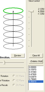
figure 2, Slice Control |
The Cylinder Generator uses slices along the cylinder
to capture data points. If the hit count is set to 10 and the slice count is
at 5, then there are a total of 50 data points. The slices are created
equally over the distance from end point one to end point two.
To change the slice count, use the Up/Down arrows in
the slice control, or enter a new value. As you click on the arrows, the
graphic will update showing the new slice count.
If the cylinder has a groove in it, a slice may pass
over that groove which would create a poor fit. To prevent this, locate the
slice in the list and press the <Delete>/Add button, or double click. The
slice will highlight and be removed from the path generation.
Creating Offline IPs and Automatic IPs
Once the Clearance Coordinate System has been
established and set active, Offline IPs can be generated to build a motion
path for safe CMM travel,
see Offline IP Generator.
Special Interim Point Commands
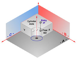 |
| figure 3, Entry IP |
In most applications, the use of the command <Add
Entry IP> and <Add Exit IP> will ensure safe transition for your CMM into
and out of features. The use of these commands requires that a Clearance CS
is currently set active. For a cylinder, Entry and Exit IPs will move
parallel to the axis of the cylinder, see figure 3.
The Add Entry IP command will calculate an IP from the
first SO along the axis of the cylinder into the Clearance CS XY base plane.
Referring to the illustration at right, the first Standoff Point is
extracted and projected into the XY Base plane of the active Clearance CS.
The motion will start directly over the hole and plunge to the first SO
safely.
The Add Exit IP command creates a similar IP to Add
Entry IP except it will use the last SO as the reference.
Miscellaneous Functions
<All Around>
This will recalculate the motion to measure all around the circle. When
there are 4 data points, each data point will measure at:
- Data Point #1 - 0°
- Data Point #2 - 90°
- Data Point #3 - 180°
- Data Point #4 - 270°
The motion path generator will determine optimal path including the
insertion of IPs between data points to prevent collision with the part.
This is especially important when measuring outside diameters.
<Defaults>
Geomet has built in defaults for feature generators. In the cylinder
generator, the Default command will create a 24-point feature consisting of
4 slices and 6 points per slice and uses the current Start and Stop Angle
settings.
Translate Endpoints
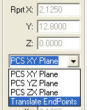 |
figure 4,
Translate EndPoints |
The Translate Endpoint command is a relative adjustment command which
will offset the current XYZ values of each endpoint a specified distance.
This is helpful when measuring similar features. An example would be a
series of five 0.500" diameter holes 1.00" apart in the X direction. Build
and execute the first hole using the Cylinder Generator. When the feature
has been completed, activate the Cylinder Generator and the last nominal
values will be displayed, or in this case, the parameters of hole number
one.
From the drop down selector, choose [Translate Endpoints]. Enter 1,0,0 in
the Relative Adjustment group and press <Ok>, the end points will translate
by the XYZ values. Follow that by updating the Entry and Exit IPs if
required. Press the <Execute> command and the CMM will engage motors and
measure hole number two following the motion path built by the Cylinder
Generator.
Interpreting the Graphical Display
A Cylinder can be orientated in any direction within a 3D space. This
makes it difficult to use a 2D display to properly represent it.
 |
 |
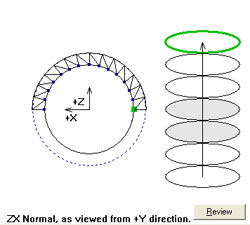
| figure 5, As shown in Generator |
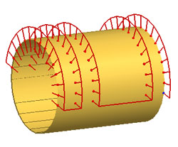
figure 6, As shown in
Inspection Report |
In figure 5, is shown how the cylinder is constructed in the Cylinder
Generator. Figure 6 is the final solution shown in the inspection report
showing the motion path. As you can see, there are two slices deleted and
the path reverses direction between CW and CCW with each slice.
In the Generator, the CMM axis directions are shown, here they are +X /
+Z and the data points are captured on the top to allow clearance for the
probe shank. With some practice, you will understand the intricacies of
building an efficient and safe motion path.
<Review>
This command is useful when learning to use the Cylinder Generator. As
shown in figure at the right, the Review command displays the current
settings and highlights any potential problems. In figure 7, we see a
highlight ***CAUTION*** indicating there are no Entry or Exit IPs in
the motion path.
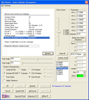 |
| figure 7, Review |
The motion path does not show a clear path into the cylinder and out of
the cylinder. You have to choose if this is acceptable based on your part.
To return to the graphic display, press the <Review> button again.
|


