Command Activation
| Ctrl + z |
Measure→Auto Features→Circle Generator |
|
| Keyboard |
Main Menu |
Toolbar |
Definition
The Circle Generator feature builds and tolerances 2D circle features. This allows building of
offline features when not connected to a coordinate measuring machine or
when the
production part is not available. The Circle Generator also provides tools
to build all motion path and can execute on demand the measuring of the new circle.
The Circle Generator provides complete access to size,
location, sweep and motion path required to measure the feature. The tool
has two functions, the first is to create new features, it also provides
access to editing an existing feature whether created by the generator or
manually taught.
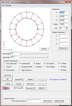 |
| figure 1,
The Circle Generator |
Using the Circle Generator to Create a New Feature
To create a new feature, activate the generator and
follow these steps:
Step 1 - Feature Characteristics
Complete the selections in the Feature Characteristics
Group
- Select Inside or Outside feature type.
- Choose reporting format, Radius or Diameter.
- Choose probing direction, Clockwise or
Counter-Clockwise.
- Select the projection plane, XY, YZ or ZX.
Step 2 - Feature Parameters
Complete the values required in the Parameters Group
- Enter the XYZ Circle Center.
- Enter the Radius or Diameter.
- Select the number of hits required.
NOTE: when entering the XYZ center location it is
important that you establish a probing depth sufficient to clear chamfers
and edges. For example: if the bore being measure is in the current PCS XY base
plane and piercing the PCS base plane at Z = 0.00 the center point would have the XY
values entered directly in PCS values, but the Z component would be entered
as a negative number, such as a -0.100". When the motion is
executed, the data points will be captured at a depth of -0.100" below the
surface.
Step 3 - Motion Path Adjustments
There are several tools available to build motion
paths to ensure clear motion without collision into the inspection part, clamps and other obstacles. These include Clearance Coordinate Systems,
offline IPs and Automatic IPs.
Clearance Coordinate Systems
A complete description on Clearance Coordinate Systems can be found here.
Creating offline IPs and Automatic IPs
Once the Clearance Coordinate System has been
establish and set active, Offline IPs can be generated to build a motion
path for safe CMM travel, see Offline IPs.
Auto-Search Circle Edge
The Circle Generator can search from the estimated center to the circle edge along the defined starting angle to commence capturing data points.
To use the Auto-Search routine, position the probe near the actual center of the circle. The search direction is determined by the Start Angle that is set either by using the Start Angle slider control or by entering a value in the data field.
Enter the estimated search distance in the data fields labeled "Max. Search Distance". This value should represent the radius of the circle.
Press the <Start Search> button and Geomet will engage the DCC motors and move from its current location along a vector defined by the Start Angle. Once contact is made with the edge of the circle, the Circle Generator will calculate the motion path required to measure the circle and commence measuring the circle based on the parameters set in the Circle Generator.
NOTE: Set the Start and Stop Angle, number of hits and orientation parameters prior to using the search command.
Update Center
The <Update Center> button will reset the Circle Generator to use the current XYZ probe position as the center of the anticipated circle. This is an optional command to center the displayed pre-motion path around the probe position.
Special Interim Point Commands
In most applications, the use of the command <Add Entry IP> and <Add Exit IP> will ensure safe transition for your CMM. The use of these commands requires that a Clearance CS is currently set active.
The Add Entry IP command calculates an IP directly over
the feature in the normal base plane. For example, in the XY circle example,
the first Standoff Point is extracted and projected into the XY Base plane
of the active Clearance CS. The motion will start directly over the hole and
plunge to the first SO safely.
The Add Exit IP command creates a similar IP to Add
Entry IP except it will use the last SO. The combination of these two
commands results in the CMM moving directly over the first SO, perform the
measurement and exit the hole safely.
Miscellaneous Functions
Execute
This command acts upon the values displayed in the
Circle Generator and instructs the CMM to perform the inspection.
All Around
This will recalculate the motion to measure all around
the circle. When there are 4 data points, each data point will measure at:
Data Point #1 - 0°
Data Point #2 - 90°
Data Point #3 - 180°
Data Point #4 - 270°
The motion path generator will determine optimal path
including the insertion of IPs between data points to prevent collision with
the part. This is especially important when measuring outside diameters.
Defaults
Geomet has built in defaults for feature generators.
In the circle generator, the Default command will create a 16 point feature
using the All Around motion path generator.
Relative Adjustment
The Relative Adjustment command will offset the
current XYZ values a specified distance. This is helpful when measuring
similar features. An example would be a series of five 0.375" diameter holes
1.00" apart in the X direction. Build and Execute the first hole using the
Circle Generator. When the feature has been completed, activating the Circle
Generator will display the last known values, or in this case, the parameters
of hole number one. Enter
1,0,0 in the Relative Adjustment group and press <Perform Adj>, the hole
center XYZ values will update and if you are using Entry and Exit IPs, just
press the Execute command and the CMM will transition and measure hole
number two.
Review
This command is useful when learning to use the Circle
Generator. As shown in figure 2, the Review command displays the current
settings and highlights any potential problems. Here we see a highlight
(***CAUTION***) indicating there are no Entry or Exit IPs in the motion
path.
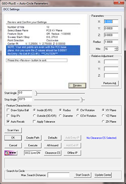 |
| figure 2,
The Circle Generator Review |
The motion path does not show a clear path into the
circle and out of the circle. You have to choose if this is acceptable based
on your part. To return to the graphic display, press the <Review> button
again.
|


