|
Command Activation
| |
Measure→Macro Routines→Bolt Hole Generator |
|
| Keyboard |
Main Menu |
Toolbar |
Definition
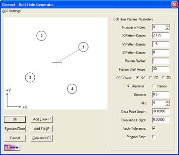
The Bolt Hole Generator is a multi-feature routine
that can create 2 or more inside diameter or radius 2D circle features.
These features surround a common center point which is defined in the
current Part Coordinate System.
 |
| figure 1,
Bolt Hole Generator |
To begin the Bolt Hole Generator, select from
the main drop down menus, [Measure→Macro Routines→Bolt Hole Generator].
Geomet will display the generator as shown in
figure 1.
Using the Bolt Hole Generator
The generator can create new features by inserting
program steps during the self-teach or offline modes. It can also create and
execute the all motion required. This directs the motorized CMM to measure
all features associated with the Bolt Hole Pattern.
Building a Bolt Hole Pattern
Step 1
Launch the Bolt Hole Generator. Main drop down
menus; [Measure→Macro Routines→Bolt Hole Generator].
Step 2
Select the required Number of Holes, the
minimum is 2.
Step 3
Choose the center of the bolt hole pattern.
Example: the bolt hole pattern is centered at X=5.000", Y=4.500" in the
PCS XY base plane at a Z=1.000". The Z component controls the height of
the surface where the Bolt Hole Pattern is taken from. In figure 2, we
show the Bolt Hole Pattern on a surface above the PCS, 1.000".
Step 4
Choose the reporting format, Diameter or Radius.
Step 5
Set the size of the holes in either Diameter or
Radius based on the chosen reporting format.
Step 6
Establish the starting hole position in angle
deviation. In the example shown, the angle is set at 30° and is
represented by a blue dashed line from the pattern center to the first
feature.
Step 7
Choose the correct PCS Base Plane, XY, YZ or ZX.
Step 8
Set the number of hits per hole.
Step 9
Choose the depth the motion path generator will
use to capture data points. In this example, the probing depth would be
set at -0.100" to allow safe probing below the surface. In figure 2, we
show the 4 circle Volt Hole Pattern on a block 1.000" off the XY base
plane of the PCS. Our probing depth is represented by the blue line
which is set at 0.900". This is the result of the nominal height
(Z=1.000") adding the Probing Depth (-0.100").
Step 10
Choose a Clearance Height value which determines
the safe height between holes for the CMM. In our example, the probing
distance is set at 0.900", the block height is 1.000" and we will use a
Clearance Height of 0.500". When the CMM moves from one feature to the
next, it will move to the Clearance Height, Nominal Height (1.000") plus
Clearance Height (0.500"). The CMM will move at Z=1.500" between
features.
Apply Tolerance
By placing a check next to this option, Geomet
will attach relevant tolerance data to the feature when it is created.
Program Step
When this option has been selected, all features
created with the Bolt Hole Generator are linked together to form one
macro feature. When they are linked together, they can be edited in the
part program with the Bolt Hole Generator tool. The Bolt Hole Generator
will insert a program step "Bolt Hole Variable Parameter" which contains
the bolt hole pattern characteristics and links to all the features
associated with the pattern.
|
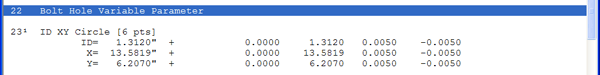 |
| figure 2, Bolt Hole Parameter Record |
For example, in manufacturing the bolt hole
pattern consisting of 36 holes might require two operations. The first
operation bores each hole at a diameter of 1.000". The second operation
inserts a bushing reducing the diameter to 0.750".
Create an inspection program to measure the first
operation using the Bolt Hole Generator to build the 36 holes. Place a
check next to Program Step and create all features by choosing <Ok> to
create the features offline, or <Execute/Close> to instruct CMM to
measure the feature immediately. Save your inspection with a unique name
identifying it as the first operation.
|
 |
|
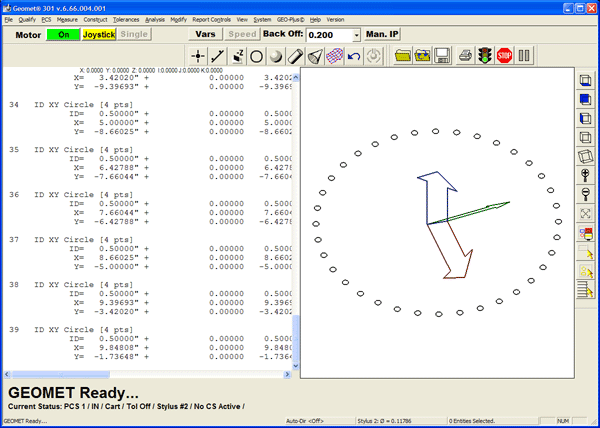
figure 3, Bolt Hole Pattern |
Edit the Macro Program Step
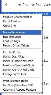 |
| figure
3, Editing the Bolt Hole Pattern Parameters |
To edit the parameters used to create the Bolt
Hole Pattern
operation based on the first manufacturing operation, open the file and highlight the Bolt Hole Parameter
record, or any feature within the bolt hole pattern and press the right
mouse button. A sub menu will appear, see figure 3.
Choose Macro Parameters which will activate the
Bolt Hole Generator to allow changing the location, size and number of
hits. Some details will be protected such as number of holes and PCS
projection plane. Edit the size of each hole to a diameter of 0.750" and
accept the change. All linked features will update with the new
parameters. Save this change with a unique file name referencing
operation number two.
|


