|
Introduction
Direct Computer Control, commonly
known as DCC,
is the process where
Geomet controls the motion of the CMM to
perform part inspections and higher level functions such
as scanning operations. Every feature in Geomet can have motion attached to it. For
example a Point would contain the necessary motion to traverse to the approach vector for
the point to capture, slow to a probing speed and capture the data point
then retreat to a stand off position. All the
information for the moves is contained in a Motion Map which is attached to the feature.
Geomet initially creates the motion map through a process of "learning" as
the operator measures the part being inspected the first time. On Helmel CMMs, this
process can be done either using the Joystick controls, or by turning the motors off and
moving the CMM by hand. All motion is considered Point-to-Point where every start and end
point consists of one of the following point types:
IP points are XYZ positions captured during the
self-teach process that are required to provide safe passage for the probe to clear
obstacles. IP points are also are used to establish the vector approach for measurement data
points. see figure 1.
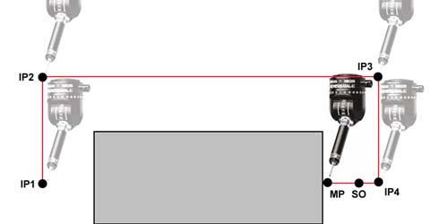 |
| figure 1, Motion Path |
In the example above, we show a motion map moving from IP1, which corresponds to the
retract position of the last feature, to the next Measurement
Point (MP) of the current
feature. The operator would capture the current position (IP1) by pressing the
<IP>
button on the joystick. The CMM would then be positioned to IP2 and again the
<IP>
would be pressed. This continues until position IP4 has been reached. The move
after IP4 captures the data point MP.
The operator chose the path IP1 -> IP2 -> IP3 -> IP4 to allow safe
passage for the probe around the part. The motion defined as IP4 to the MP is considered the approach
path. Geomet will calculate the Stand Off (SO) point based on the stand off distance
defined in the DCC parameter settings. If the distance from IP4 to MP is greater than the
stand off distance, the SO will be inserted as shown in figure 1. If the distance from IP4
to MP is less than the distance define as the stand off distance, then IP 4 becomes the
SO.
There are two Stand Off points created, one before the MP and one after. Both of these
SO point share the same XYZ location. The first SO is where Geomet will switch from
Traverse Speed to Probing Speed. The second SO which follows the MP is the retract
position and the completion of a normal feature motion map.
This point brackets the Measurement Point. The
preceding SO will act as the location the motion of the CMM will slow to the Probe Speed.
The SO that follows the Measurement Point is the location the probe will retract
towards after
the MP point has been captured.
The MP point is the point of contact where the
probe contacts the part.
As the name suggests, the Auto-IP is calculated
at the moment it is used during motion. This point is used when Geomet has an
Clearance
Coordinate System established. The Auto-IP is define not by an XYZ location, but by an
axis of movement. If the Auto-IP is defined as using the Z axis, then the motion will
calculate a direct path from the current location into the XY plane of the current
Clearance Coordinate System. The actual motion will be parallel to
the Z axis of the Clearance CS.
The teaching of the motion path can be accomplished when motors are on and the operator
uses the joysticks, or when the motors are switched off and the operator moves the CMM by
hand. Manual operation is often the preferred method of teaching due to the speed and ease
of movement when the operator moves the CMM by hand. However manual or joystick motion can
lead to erroneous IPs when moving the CMM at a high speed.
For example, the CMM interface is responsible to control all communications between
Geomet and the PMAC motion controller. The interface polls the PMAC motion controller at a
variable rate such as 5 times per second and transfers position and status data between
Geomet and the PMAC motion controller with each cycle. The buttons on the joystick are
interpreted by CMM interface and transferred to the motion controller at the interface
polling rate. Therefore, when the IP button is pressed while moving 10 inches per second,
the actual capturing of data can happen at worse case, 0.2 seconds later, or 2 inches
after you pressed the IP button! The procedure of capturing an IP starts with the IP
button press. Then the CMM interface acknowledges the button press and sets a flag to
inform the motion controller to capture an IP and return the XYZ position. This requires
one cycle. Therefore when teaching a motion path that requires positional accuracy, slow
down or stop at the IP positions.
The PMAC motion controller maintains the current position of the CMM at rates higher
than 8MHz per second. When a probe trigger occurs, PMAC latches that position in memory
and waits for the CMM interface to cycle around before transmitting the positional data to
Geomet.
Geomet Motion Adjustment Tools
Motion paths often require adjustments due to changes in the part or the need to adjust
motion to eliminate accidental collisions due to a missing IP or other conditions. These
adjustment tools are:
|
Motion Edit Tool |
Allows full adjustment of the motion map
by allowing access to adjust a all or a single motion point. Appending, Inserting and
Moving of motion points can be done. |
|
CMM Homing |
On DCC style CMMs, a initialiation of the motion control system is required to establish a point of reference for the XYZ scales. This process is known as CMM Homing. |
|
One-Step Edit |
This tool will provide access to adjust
motion attributes (speeds and distance) or move the entire motion map a desired relative
distance. |
|
DCC IP/MP XYZ Targeting |
Accuratly position the probe under DCC control to capture MPs or set IPs. |
|
DCC Settings |
Provides access to
the speed and distance parameters used in the building of a motion
path. |
|
Motion Path Tests |
Building a motion
path requires certain conventions to be followed. Should a common
error, such as missing IP or SO points, or distance too small, the
Geomet Motion Paths Tests will report common errors. |
|
Point Targeting |
In certain
conditions it may be important to hit the exact position called for
in the motion path. An example would be the capturing of a MP on a
knife edge. |
|
Clearance Coordinate
Systems |
Clearance Coordinate Systems (CS) are defined as
an offset to an existing PCS and is used to provide safe transition
planes for CMM movement. |
|
Offline IP |
The Offline IP generator allows the creation of
Interim Points at the beginning of a motion map. These points can be
created as a XYZ defined point or as a Auto-IP which utilizes
Clearance CS for safe transition. |
Geomet Feature Generators
|
Point |
Creates 1D, 2D and 3D Point Features in offline and interactive modes. |
|
Line |
Creates 2D Line Features in offline and interactive modes. |
|
Circle |
Creates 2D Circle Features in offline and interactive modes. |
|
Cone |
Creates a Cone Feature in offline and interactive modes. |
|
Cylinder |
Creates a Cylinder Feature in offline and interactive modes. |
|
Plane |
Creates a Plane Feature in offline and interactive modes. |
|
Bolt Hole |
Creates two or more 2D Circle Features surrounding a common center point in offline and interactive modes. |
Motion Map Test
Geomet offers a test to ensure the motion map is consistent with the rules of motion as
define by Geomet. The test definitions can be found
here.
|


