Geomet home
Target Homing Tool
Search tool Information index
 
       
7.01.196 Geomet Junior+, 101, 301, 501
       
  Command Activation
 
  Target Homing Tool
 

Target Homing is a tool provided in Geomet to perform unassisted DCC moves for the purpose of positioning, setting IPs and capturing MPs. Knowledge of this tool greatly enhances your control over the CMM and the motion path on all classes of inspection from easy to complex.

To launch the Target Homing tool, press <F4>.


Target Homing

Coordinate System Selection

The Target Homing tool allows selection of the coordinate system to move within. To choose the coordinate system, place a bullet next to the choice.

NOTE: The selection of the Current PCS uses the active Part Coordinate System. If you require to move inside a different PCS, that PCS should be set active before using the Target Homing tool.

Coordinate System Selection

Position Reference Selection

The XYZ Target Position values can be entered as actual target positions or as relative moves from the current location. Select the Position Reference by placing a bullet next to the choice.

Position Reference

Target Position

The data fields labeled as Target Position are used with the functions <DCC Move> and <Move / Set IP>.

Enter the XYZ Target Position for the position to move then press:

  • <DCC Move> Moves the probe to the target XYZ location without adding an entry into the current motion map.
  • <Move / Set IP> Moves the probe to the target XYZ location and adds a new IP entry into the current motion map.
Target Position

Step and Repeat

The Step and Repeat tool provides a relative additive update to the entered Target Position after <DCC Move> or <Move / Set IP>.

To set the XYZ values, press the <Setup> button. The Edit Value entry form appears where you would enter the XYZ relative values. Simply put, if you want to move in the X direction 1.000" each move, then enter X: 1.000, Y: 0.000 and Z: 0.000.

Accept the setup values by pressing the <OK> button.

Place a check on the Activate option and then after each move the Target Position values will have the Step and Repeat XYZ values added to it.

Step and Repeat

Enter Step and Repeat values


Measurement Point Tools

One very powerful tool provided with Target Homing is the ability to capture Measurement Points under DCC control using a variety of targeting methods.

To access the Measurement Point tools, press the button <MP Point>.

There are 5 options of MP capturing methods provided with this tool. They are:

  • XYZ Target
  • PCS Axis
  • IJK Vector
  • IR Radial
  • OR Radial

Each method provides unique targeting capabilities to ensure your captured MP Points are on the expected target.

MP Point Tool

Motion Path Building

The use of this tool is to compliment the self-teach process of building a motion map for a feature. As you build your motion map, normal operations have you moving and setting IPs to ensure a clear path. While the Target Homing tool is active, you should continue to build and set IPs using manual IP operations or the Target Homing <Move / Set IP>.

The use of the Measurement Point tool will capture a MP and add to the motion map the proper SO-MP-SO combination under DCC control.


XYZ Target

This method is the simplest of all options. Enter a XYZ Target in current Part Coordinate values and upon pressing <Measurement Point> the DCC system will drive toward that XYZ point expecting to make contact.

The distance it travels is limited to the entered value in the Max. Search Distance field.

XYZ Targeting

PCS Axis - No Target Specified

This method captures an MP while moving parallel to the current PCS along the direction specified in the Select PCS Direction.

Select the direction of movement by pressing one of the button in the "Select Probe Direction" group. Control the length of search with the "Max. Search Distance".

To commence capturing an MP, press the button <Measurement Point>. Under DCC control, the probe will seek contact withing the search distance. Upon capturing the MP, the probe will retract to the SO distance.

PCS Axis

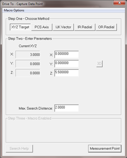
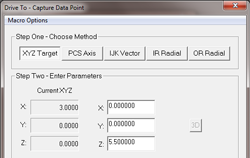
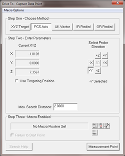
PCS Axis - Specified Target

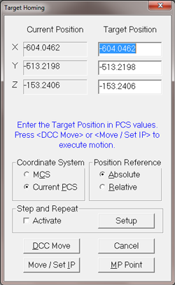
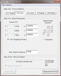
The method is similar to the described method above except a specific XYZ target position is added. This is activated by placing a check next to "Use Target Position".

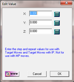
Enter the XYZ target position in the provided data fields. Then press the <Measurement Point> button and the Target Homing tool will calculate a path to the target MP as two motion paths.

The first path traverses to a point directly over the MP target and then changes direction and executes a MP capture move.

For example, if the current position is:

X:1.000, Y:2.000, Z:2.000

The MP target using a -Z direction is:

X:5.000, Y:5.000, Z:-1.000

The traverse motion path will move parallel to the XY plane at a constant Z=2.000 until reaching X:5.000, Y:5.000 then switch to a MP capture move down to the target MP position.

PCS AXis Specified Target

PCS Axis - Macro Routine Set

To enhance MP capture capabilities, the PCS Axis method provides multi-point capture routines that not only captures more than one MP point, but also creates measured features and solutions. The three macros are:

  • 1D Point - 1D Point- 1D Distance
  • 1D Point - 1D Point - 1D Bisect
  • Slot - 1D Width

As this method works in motion parallel to the current PCS, it is ideal for creating and constraining results to 1D reporting such as slots and extended widths on radial features.

Point-Point-DistancePoint-Point-Distance

Ideal for creating two 1D points on features such as slots, key-ways and other features requiring the distance to be reported.

Point-Point-BisectPoint-Point-Bisect

Ideal for creating two 1D points on features such as slots, key-ways and other features requiring the distance to be reported.

Slot-WidthSlot-Width

Ideal for creating two 1D points on features such as slots, key-ways and other features requiring the distance to be reported.

Macro Tools


MAcro and Report Solutions


IJK Vector Method

The entered IJK value "drives" the probe toward the MP contact point from the current location.

An example would be to drive directly down in the -Z direction, the entered IJK values would be:

I: 0.000, J: 0.000, K: -1.000

Where IJK is most useful is the need to approach the MP point where obstructions are is the way such as a slot.

Slot IJK Approach

The example IJK here would be:

I:-0.707, J:0.0, K: -0.707

The approach is 45° down in the -X/-Z direction and no change in Y.

IJK Vector

IR Radial Method

This method moves parallel to a PCS base plane (2D) or Spherical (3D) and captures a MP from the current location along a vector from the current origin.

Ideally suited for capturing MP points inside a bore or fillet where the origin is the center of the feature. Position your probe inside the feature and press the <Measurement Point> button and the probe will move outward from the origin until contacting the feature surface.

IR Method

OR Radial Method

This method moves parallel to a PCS base plane (2D) or Spherical (3D) and captures a MP from the current location along a vector to the current origin. Ideally suited for capturing MP points outside a boss, rounded edges or spherical surface where the origin is the center of the feature. Position your probe outside the feature and press the <Measurement Point> button and the probe will move toward the origin until contacting the feature surface.

OR Radial Method

TIP: Using IR/OR Methods

Some features such as large radii cannot be measured using standard prismatic features such as a circle or sphere. The inherent errors on a large radii where the data points captured represent a small sweep arc would result in rather large errors in size and location.

Cases such as these, translate the origin to the nominal center of the feature and use IR or OR Point features along the available surface. Each resulting point will represent the radius with minimal introduced error.

For additional reading on these and other errors introduced on large arc measurement with reduced sweep, read Tech Note #2:

Multi-Point Feature and CMM Inherent Errors

A tutorial using IR / OR measurements can be found here.