Applies to: All levels of Geomet
Last updated:
Tuesday December 08, 2009.
The Radial Point tool is designed to facilitate measuring
large radii and 2D/3D surface point generation on radial contours.
Radial Point Refresher
A Radial Point is an invaluable tool in the inspection
process. Often overlooked, this tool can provide excellent results on
difficult-to-impossible arc or spherical features that need inspections.
Measuring large or small features often exceed the
capabilities of a CMM. Not that the CMM does not have the features to
measure these surface, it is just that the nature of stacked accuracies will
work against the inspector and deliver poor and unrepeatable results.
The Radial Point routine will minimize some of these
errors by delivering results based on a single point and not using an
algorithm that relies on several data points and a least-squares solution.
This process will aggravate the results when you have minimal data points
and a variance from the nominal shape.
For example in the technical note "Multi-Point
Feature and CMM Inherent Errors" we discuss the affects of data point
errors on the final calculation of size and location of a circle and how the
results can be reported in error compared to actual known values.
Here is where then Radial Point will deliver the results
you expect.
Remember the Indicator?
Inspectors that had the privilege of working with an
inspection plate, indicators, squares, paper and pencil know fully well the
limitations of projected radius inspections. Technology can not replace the
inherent knowledge of inspectors that have years of experience measuring
this way.
The Radial Point feature in Geomet is developed based on
old-time inspection technique and knowledge......one point.......one solution.
Example #1 - 2D Large Diameter Inspections
The production part you are tasked to inspect has a radius
of 25", but your part only offers a small slice of the total
circle.
Attempting to measure this radius as a arc would result to
poor repeatability and a loss of confidence in the inspection process.
To perform this inspection, start by establishing the
coordinate system for the part based on the example below.
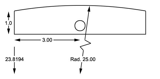
The coordinate system origin is located in the lower left
of the block. Once the coordinate system has been establish, you are now
capable of translating within the coordinate system to create a new origin
at the center of rotation for the 25.00" radius.
Translate the origin X= 3.000" and Y= -23.8194". This will
place the XY origin at the expected center of the 25.00" radius.
For best results, we suggest that you change the reporting
format to Polar mode. This is handled by a keystroke < e > that toggles
between Cartesian and Polar modes. Now set the CMM up for Outside Radial
Points which is keystrokes < 7 + 2 >, or by using the features toolbar and
the Point icon.
Geomet will prompt you to capture an XY OR Point. Capture
a single point along the radial surface and it's polar position and radial
length will be added to the report. Continue capturing several points along
the radial surface. Each point will be reported individually.
Notice that the Radial Length is at or around 25.00". The
strength of this inspection method is that each point captured is only
affected locally by CMM inaccuracies and Touch Probe inaccuracies, not an
algorithm that negatively affects the results due to poor point distribution
along a small sweep length of the ac feature.
For example, Let's solve the above example using a 3-Point
Circle routine and that the part being measured is exact to print. Two of
the data points captured are exactly at 25.00" polar distance from the
center of the circle and one point is 24.9998". The reported results are:
| Description |
Value |
| X |
0.0011" |
| Y |
0.0208" |
| Radius |
24.7920" |
As you can see the radius is 24.7920"
or 0.2080" off nominal! Should the tolerance being applied is ±0.010, you
have now rejected the part.
Let's expand this same measurement by
capturing another 3 data points where again two of the points are exactly
25.000" polar length from the arc center and one is 24.9999". The new
calculated radial size is 24.9896" still 0.0104" from nominal. With just a
single point error of 0.0001" you can not rely on the circle function to
provide you with a sound and consistent result.
Why does the Radial Point work?
The reasoning is simple, there are no multi-point
algorithms to influence the results. A single Outside Radial Point solves a
simple point-to-point solution and then compensates for the stylus size. The
most error you can expect to see will be the repeatability errors of the
touch probe which typically remain less than 0.0002"
3D Spherical Measurements
Don't limit the usefulness of the Radial Point to just 2D
applications. There exists both the Inside and Outside Radial Point routine.
Once you have established your Part Coordinate System, translate the origin
to the center of the Spherical feature. Activate the appropriate 3D Radial
Point routine and capture data points along the surface.
When in Polar reporting mode, the polar length is the
radius of that surface at every point!


