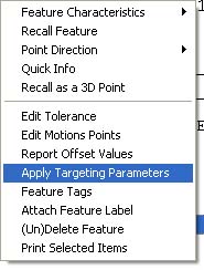
Targeting rules can be attached to 1D, 2D and 3D Point features. To assign, highlight
the feature in the inspection report and activate the sub menu by right clicking,
see
figure 1. Choose [Apply Targeting Parameters] from the menu.
This command will activate a dialog where you can set targeting parameters,
see
figure 2.
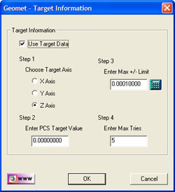 |
| figure 2, Target Parameters |
There are four steps used in setting the targeting characteristics.
Every step must be completed and the "Use Target Data" must be checked for the
operation to be completed.
Step 1 - Choose Target Axis
Targeting is designed to allow exact control on one axis at the point of capturing a
data point. As shown in figure 3, we can target a surface such as a knife edge by
controlling the Z axis.
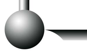 |
| figure 3, Z Axis target on a Knife Edge |
Step 2 - Enter PCS Target Value
Using the example is figure 3, we first start be ensuring the Part Coordinate System
has been established on the top surface. Our Z axis target would then be 0.00 which
ensures the probe contacts the edge at the equator of the stylus.
Step 3 - Enter Max +/- Limit
All systems that have drive capabilities, whether it is a CMM or a CNC Mill, will
attempt to move along a target vector starting at a given XYZ point 1 to a XYZ point 2. If
it was possible to chart the deviation while in motion, you will see a small deviation
from the actual position to the target vector. This is referred to as a dog leg effect or
tunneling.
The value you enter in step 3 should reflect a small enough value to allow the DCC
controller to follow the motion vector, yet large enough not to produce poor results by
capturing the data point to far from the stylus equator. In most examples, a value of
0.00015" works well.
Step 4 - Enter Max. Retries
During the inspection process, Geomet will drive to the designated measurement point.
Should it identify that point to be outside the limits on the controlled axis, Geomet will
return to the stand off point before the measurement point. When it returns the the SO,
the speed will be reduced 50% and Geomet will attempt to capture the data point again.
This cycle is continued until either the max tries values has been reach, or the target
position on the controlled axis falls within the max limit established in step 3. You will
notice the Geomet displays the missed value on a small dialog while in the re-measure
cycle.