|
Definition
Before Geomet can perform an inspection, there must be at least one qualified stylus in
the current stylus database. Geomet requires the size and MCS location of the stylus to
correctly apply stylus compensation to measured features.
The qualification process is designed as a step-by-step process that will provide clear
instructions to the operator for each process required to complete the qualification. For
example: The qualification of a single stylus using an electronic touch probe, such as the
Renishaw TP-ES, requires only two steps. Those steps are the selection of a ball style
qualification, followed by the actual capturing of data points on a reference sphere.
A more complicated qualification may include a PH10 motorized probe head. The
qualification process will automatically scale to include a selection tool to
identify the A / B angles of the motorized probe head prior to capturing data points.
The qualification process is determined by the hardware attached to your CMM. To review
how Geomet is configured for your attached hardware, please see the Probe
System Setup Tool located in the drop down menu Qualify.
Choose from the examples below the qualification process required for
your CMM
 |
| figure 1, Single Position Ball Stylus |
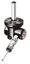
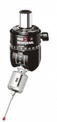
This Qualification example is based on the hardware configuration consisting of a ball
stylus touch probe on a electronic probe head, see example in figure 1. These
might include the Renishaw TP-ES or a PH1 with a TP2 probe body.
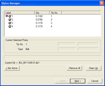
Step 1
To start the qualification process, activate the stylus manager by pressing the
<w> key on the keyboard or the
[Qualify→Stylus Manager] from the
drop down menus.
|
 |
|
figure 1, Stylus Manager |

To add a new stylus qualification, press the <Next> button found on the Stylus
Manager. Note: For more efficient operations, the Next button is also activated by
pressing the <Enter> key on the keyboard.
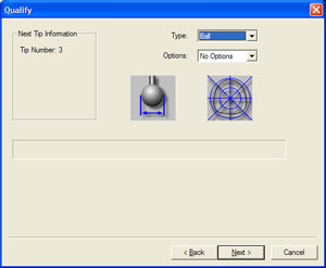
Step 2
The next step will prompt you to enter the qualification type. This describes the type
of stylus attached to your system. The choices are ball, taper, cylinder, video cross hair
and manually entered diameter.
 |
|
figure 2, Select Qualification Type |
By default the qualification type will show "Ball". To continue the
qualification process, press the <Next> button on this dialog or press the
<Enter> key on the keyboard.
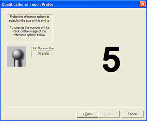
Step 3
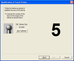
The final step will prompt you to proceed capturing the data points required to solve
the qualification of the current stylus.
 |
 |
| figure 3, Manual Qualification |
figure 4, DCC Qualification |
In figures 3 and 4, we are prompted to capture the current default number of data
points required. At this time, capture the data points on the reference sphere and the
count required will descend until all data points have been captured. The process used to
capture the data points will influence the quality of the solution. If you were to capture
your data points close together, there can be error introduced in the end result of size
and location.
We recommend that when using 5 data points, the first point should be taken on the top
of the reference sphere and the remaining 4 taken at the equator.
Should you require to abort a single data point that has been captured, press the
<F2> key on the keyboard and the required count of data points will increase as it
discards the last data point in the buffer.

When you have a DCC style CMM, the qualification countdown screen include a button
labeled <Auto Calibration>, see figure 4. This is used to qualify under DCC
control a single ball stylus in the down position. To auto calibrate, move your ball
stylus directly over the reference sphere and press the <Auto Calibration> button.
You will be prompted to manually capture a data point directly on top of the reference
sphere. Once you have captured the data point, you will be prompted to begin the
calibration. Geomet will automatically capture 13 data points on the reference sphere
under DCC control.
Once the data points have been captured, Geomet will solve for the size and location in
the MCS of the stylus and return to the main Stylus Manager screen.
Summary
Qualifying the ball stylus consists of the following steps:
 |
|
figure 5, Qualification Steps 1, 2, 3 |
This Qualification example is based on the hardware configuration consisting of a ball
stylus touch probe in different locations attached to one or more electronic touch probes.
One example would be a manual articulating electronic probe head, see example in
figure 6. Another example would be a Multiple Probe Body with electronic touch
probes, see figure 7. The final example would be a Cluster probe located on an
electronic probe with multiple ball styli installed, see figure 8. These are just
3 examples of multiple ball electronic touch probe configurations.
 |
 |
 |
| figure 6, Articulating Electronic Probe Head |
figure 7,
Multiple Probe Body |
figure 8,
Stylus Cluster |
The process of qualifying more than one physical location involves the same steps as
described above in
Basic Ball Style
Electronic Touch Probe. The first probe should be qualified exactly as stated in steps
1-3. When the first probe has been qualified, you will return to the main screen of the
Stylus Manager. To add another position on a cluster, or another location on a
articulating probe, follow steps 1-3 described above.
Geomet will qualify the MCS location and size and assign the next stylus tip number to
the stylus database. The location it stores is the XYZ variation from stylus tip number 1.
| On
DCC style CMMs there is a "Home" position which is repeatable for inspection
results. The MCS origin is the Home position of the CMM. This allows adding additional
stylus positions to the current stylus database without loss of position. On manual CMMs
that do not offer a Home procedure, the origin of the MCS is the location the CMM was at
at the time of power up, or the location when Geomet was launched. Therefore the origin
position of the MCS is not reliable or repeatable. When you qualify multiple positions,
all qualifications should be done during one session to ensure correct relationships
between all the stylus centers. Should you have to add positions after a system restart,
you should always clear your stylus database and add all positions required for your
inspection. |
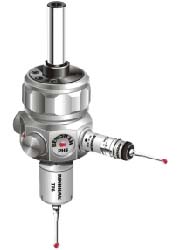
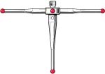
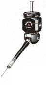
The qualification of a motorized probe head such as the Renishaw PH10T or similar
involves a another step which provides access to setting the A / B position of the head.
This step as shown in figure 9 follows the qualification type screen shown in figure 2.
 |
 |
| figure 9, Renishaw PH10T |
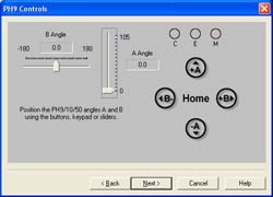
figure 10, Angle Position Selection |
Setting the articulated angle of the PH9/10 can be accomplished by using either
the Renishaw supplied hand control, or through the use of Geomet's dialog shown in figure
10. Through the use of the dialog, you can use the sliders for the A / B angles by
left-clicking and holding down on the pointer associated with the angle you wish to change
and moving or "sliding" to a new location. An optional method involves
left-clicking on the symbols +A, -A, +B, -B, and Home. With each click, the probe angles
will change one position. NOTE: The symbols are also mapped to the number key pad on
the keyboard. The table below in figure 11 shows all the mapped keys:
| Keystroke |
Function |
| 2 |
-B angle change |
| 4 |
-A angle change |
| 5 |
Return to define "Home" |
| 6 |
+B angle change |
| 8 |
+A angle change |
|
figure 11, Keystroke Table |
Once you have articulated the probe head into the correct position, continue with the
qualification by selecting the <Next> button.
Summary
The necessary steps involved to qualify a stylus attached to the motorized probe head
are as follows:
 |
|
figure 12, Required Steps to Qualify with a
Motorized Probe |
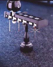
The example provided here involves the use of a Stylus change rack such as the Renishaw
MCR20 or SCR200 as shown in figures 13 and 14. The change rack allows the use of several
stylus configurations that are magnetically attached to the corresponding probe body. The
use of the stylus change rack is controlled through the use of a graphical interface
provided by Geomet to control the location and orientation of the rack in the MCS. The
setup procedure of a stylus rack can be found in the
drop down menu [Qualify→Probe System
Setup Tools].
 |
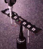 |
figure 13, MCR 20
Stylus Change Rack |
figure 14, SCR200
Stylus Change Rack |
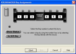
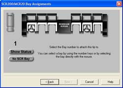
During the qualification process, Geomet will insert a bay selection setup page which
instructs the operator to the necessary steps required to install a module and qualify
that position, see figure 15. This page is placed after the qualification type
screen shown in figure 2.
 |
|
figure 15, Bay Selection |
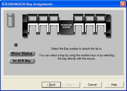
The Bay Selection page can be expanded to show the current assignments by selecting the
"Show Status" button, see figures 16 and 17. In figure 16, the graphic
representation of the stylus rack shows no modules pre-loaded in the stylus rack and no
module attached the the probe. In figure 17, we see modules loaded in bay 1 and 5.
Additionally, we see a module loaded on the probe body which is identified as having the
module from Bay 1.
 |
 |
| figure 16, No Assignments |
figure 17, Assigned Bays |
During the qualification process, you are asked to identify the bay number used for the
selected stylus. To select a bay, left-click on the bay location directly on the graphic,
or use the corresponding number key on the number pad on the keyboard.
If you select an empty bay, Geomet will prompt you to install the probe module on the
probe body. This is done manually and care should be exercised to align the module based
on the symbols on the module and probe body. Once the module has been installed, select
the <Next> button which will proceed to the qualification page.
Should you select a bay that already has a module loaded, such as a module with a
stylus cluster attached to it, Geomet will proceed to the qualification page.
NOTE: If the module assigned to bay 1 is already installed on the probe when you select
bay 5 for qualification, Geomet will prompt you to unload the current module and under DCC
control will proceed to the safe staging area for installation of the new module.
Summary
The necessary steps involved to qualify a stylus attached to the stylus change rack are
as follows:
 |
|
figure 18, Qualification Steps with
Stylus Rack |
Qualifying with a probing configuration which includes a Motorized Probe Head and a
Stylus Change Rack requires 5 steps to complete. Please refer to
Qualifying with a Motorized Probe Head
and
Qualifying with a Stylus Change Rack
above for details on the individual steps required. The order in which the steps are
proved are as follows:
 |
|
figure 19, Qualification Step Order |
Related Procedures:
Renishaw,
System Options,
Re-Qualifying a Stylus,
Labeling
a Stylus,
Deleting a Stylus,
Duplicate a Stylus,
Default
Number Data Points,
Stylus db Manager,
Stylus Edit Control, Measuring with Multiple Styli
|


