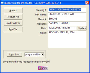
The Header Dialog provides access to the Drawing Number, Part Name, Serial Number,
Operator, Date and optional Notes. The Date field will report the current time and date
when starting a new report. The time and date can be edited by entering a new value or
updated with the <Update> button.
When starting a new inspection report, the previous values will be carried forward with
the exception of the time and date which will report the starting value. This is
especially helpful when repeating a part inspection.

The <Accept> button closes the Header Dialog and attaches the data fields to the
inspection report.

The <Recover File> button is available when returning to the previous inspection
that might have closed inadvertently. Geomet maintains a companion file when teaching a
part inspection. Should a condition arise, such as a program crash caused by events such
as a power failure, the Recover File operation will read in the previous completed steps
and the inspection can continue.
There are some limitations to a recover operation that affect the success of a recover.
For example, not all manual CMMs have a repeatable home position and when you recover, see
Setting the Home Position. If the CMM did not have a repeatable
Home position, the recovered XYZ values will not match the XYZ values when the inspection
was first done. To overcome this condition, perform the recover file operation and then
Run the file to rebuild the coordinate systems and feature actual values.
On DCC CMMs, the home position is repeatable and after a recover operation, you can
continue building your part inspection.
The recover file operation is only available when the "Save Recover Mode" is
active. By default Geomet saves the recover file. You can elect to turn off the feature by
placing a 'Yes' next to Turn off Inspection Recovery Mode in
System
Options.

As the name sounds, the command will prompt you to load a part program. Should you have
a part program opened, you will be prompted to save you current inspection.

This command will commence running the part program currently open. This is the same
command as [File→Run] from the main drop down menus.

The Header Dialog maintains a record of the last 5 inspections opened. To provides fast
access to one of these files, select from the drop down list the inspection program and
select <Load Last>, see figure 2.
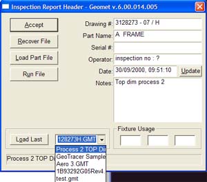 |
| figure 2, Load Last Selection |

When a new inspection is created, the data and time is
written into the record and does not change when the program is opened or
edited. To override the data and time, press the <Update> button and the
Date: field will update.

Pressing this Information / Help button, Geomet will attempt
to connect to the Internet and display the help page associated with the
Inspection Header tool.
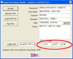 |
| figure 3, Assigning Fixture Data |
An example on using these Fixture fields would be to
identify what machining center a production part was manufactured on.
The manufacturing department may have many machining centers all making
the same part. We had one company that used over 50 machining centers
all making the same part! When it came time to measure, the operator
would type in the note section of the header the machining center ID.
Unfortunately the notes section of the header does not
provide any sorting capabilities. The Fixture Usage fields do. When
inspecting the production, enter the machining center ID in the Fixture
Usage fields and then sorting can be done to group all production
inspected on the machining center it was produced on. This is helpful
when performing SPC on production.
By default, Fixture Tracking is not active. To activate
fixture support navigate to System Options
and change to 'Yes' next to Use the fixture
data fields in the program Header.
Geomet allows the tracking of up to 3 unique inspection identifiers for a
part being inspected. We call these identifiers “Fixture Usage” from the
original purpose where a fixture ID was added to the inspection report.
An example on using these Fixture fields would be to identify what machining
center a production part was manufactured on. The manufacturing department
may have many machining centers all making the same part. We had one company
that used over 50 machining centers all making the same part! When it came
time to measure, the operator would type in the note section of the header
the machining center ID.
Unfortunately the notes section of the header does not provide any
sorting capabilities. The Fixture Usage fields do. When inspecting the
production, enter the machining center ID in the Fixture Usage fields and
then sorting can be done to group all production inspected on the machining
center it was produced on. This is helpful when performing SPC on
production.