|
Introduction
Coordinate Measuring Machines utilize scales that are mounted to each
axis of motion will require compensation. This compensation will correct for
any linear deviations identified during CMM calibration.
A certified Master Scale or Laser system is used to compare against the
reported position from the CMM Digital Readout. This deviation can then be
mathematically corrected. This information must be supplied to your CMM
software to properly measure. There are two main types of scale comparison
technologies. These are Linear and Non-Linear Compensation.
For additional information refer to
Technical Note #2.
Scales that are mounted on you CMM often required compensation to correct for
inaccuracies. These inaccuracies are the cause of scale manufacturing and scale assembly
to the CMM superstructure. To correct these inaccuracies, there are two methods the Geomet
applies, depending on conditions.
Some scales have an error that can be identified as linear error.
To identify these errors, laser readings are done at predetermined positions along the
full travel and compared to the CMM reported position. The table below shows a condition
of a pure linear error:
| Laser Value |
CMM Value |
Compensation |
| 1.00150 |
1.000 |
1.0015 |
| 2.00300 |
2.000 |
1.0015 |
| 3.12968 |
3.125 |
1.0015 |
| 4.37154 |
4.365 |
1.0015 |
| 5.95993 |
5.951 |
1.0015 |
| 7.03553 |
7.025 |
1.0015 |
The Compensation column is the value used to convert the CMM Value to read correctly as
shown by the Laser.
CMM Value * Compensation = Laser Value.
In a linear error condition, we can supply one compensation value to correct the entire
length of the CMM axis travel.
This form of compensation provides a more accurate solution for
determining scale corrections using many segments over the axis of travel. A
typical scale when mounted to the CMM can stretch and shrink over its
length. The compensation required between 10.000” - 11.000” may be different
than between 20.000” – 21.000”.
The method to determine the compensation is done by taking position
readings along the full travel, for example, every 1.000”. A table is built
using the Master Scale or Laser position and the reported CMM position.
 |
|
Non-Linear Setup Tool |
Non-Linear Setup Tool
Activating the Non-Linear Setup Tool requires that the Scale
Compensation Mode setting in System Options
is set to Multi-Position Linear Compensation.
Activating the Non-Linear Setup Tool
Keyboard: <Alt + Ctrl + shift + F2>
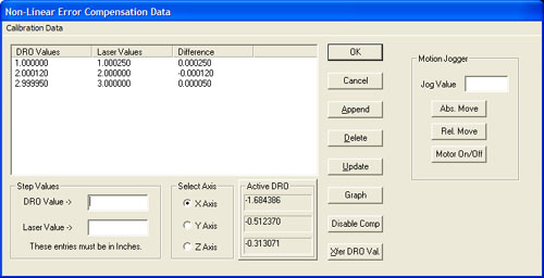
Taking a Tour of the Linear Setup Tool
Calibration Data List
The list of Master Scale or Laser readings along with its corresponding
DRO positions are shown under Calibration Data. This list does not show the
compensation value, which is calculated as:
XReference Value / XDRO Reported Value = XCompensation
Value
Selecting an entry in the data list will bring the position values down into
edit controls labeled DRO Value -> and Laser Value ->. From the edit
controls changes can be made when performing or editing a calibration.

When building the data list, new entries are added by entering the
reference and DRO positions in the Step Value Group. Pressing <Append> will
then transfer that data into the list. This list performs a sort to keep the
list in linear order.

Removes the selected position from the data list.

When a position record is selected, changes can be made to the laser and
DRO position values. Once the changes have been completed, press <Update> to
transfer the changes into the data list.

Displays a graph of the position difference values. This graph can be
printed for the current axis or for all three axes.

When <Disable Comp> is active, Non-Linear compensation is deactivated and
the CMM will use Linear Calibration. When pressing, the Non-Linear tables
are saved to the data file.

Moves the current position displayed in the Active DRO Group into the
edit control labeled DRO Value ->.
Motion Jogger Group
The Motion Jogger Group is available on CMMs that have a motion
controller.

Positions the CMM under DCC to the absolute position entered in Jog
Value.

Positions the CMM under DCC to the relative step position entered in Jog
Value.

Toggles the state of the motors between On or Off
Related Procedures:
Scale Factors,
Manual CMM Home, DCC CMM
Home
|


