General Settings
Use Tool Tip Help
Default: Checked. When checked, activates the mouse tool tip help. When active, the
mouse can be held over a button, image or other control and after small period of rest, a
help display will appear to describe the control. NOTE: not all controls in Geomet
have tool tip help support.
Use Fast Access Menu
Default: Not Checked. The Fast Access Menu option in
Geomet allows the user to navigate stored programs through a fixed menu
system. This allows single button access to load and start a part
program.
EZ Launch Menu System
Default: Not Checked. Activates the EZ Launch Menu System. This menu system offers single touch
access to one or more assigned files when used manually. When used in
monitor mode, it receives inspection program instructions from a script file for automated
operations.
Enable DCC Motors
Default: Checked on DCC style CMMs. Available on DCC CMMs. When checked, this activates the auto drive systems. When
un-checked, the drives systems are disabled and complete manual inspections can take
place. The ability to activate this option is
controlled by the GeoSecure system and requires authorization from
Helmel Engineering.
Enable LDI Line Scanner
Default: Not Checked. Available on DCC CMMs that have been built for the Laser Design Scanning
Probe. This option provides laser line scanning for
capturing data clouds over contour shapes. This option requires
authorization from Helmel Engineering.
Non-Linear Compensation
The use of non- linear compensation is set by the factory or
by the technician performing calibration on the CMM. This option involves the mapping of
your scales on the X, Y, and Z axes. See Technical Note #2 for
enhanced description.
NOTE: Do not uncheck this
option. Your CMM calibration tables will be deactivated and the accuracy
of your CMM will be affected. The calibration tables are stored in a
separate file, "Lerror.dat" which is stored in your Windows folder. If
you inadvertently uncheck this option, just reset the check mark.
OptoDyne Laser Calibration
When activated this option will utilize the 3D volumetric calibration developed in
cooperation with
OptoDyne
Inc. This provides compensation not only to the linear characteristics of the CMM, but
also corrects for any squareness and parallelism of the CMM superstructure.
NOTE: This option has been removed from Geomet
until further notice.
Skip Save Recover
Default: Not Checked. During normal operations, Geomet maintains a recovery file. This
file is updated after the completion of any feature. This requires time and resources to
open the recovery file, write the file out to the hard drive, then close the file with
every feature. During long part inspections or when operating on systems with limited
capabilities, this feature can be disabled saving time during the
process of building a part inspection.
 Enable
Fixture Reporting Enable
Fixture Reporting
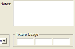
Default: Not Checked. On the Inspection Header page of
the part program, there exists three
edit controls where the operator can enter alpha numeric fixture data. Under most conditions, this is
not required. When checked, the 3 fixture edit
controls will appear, as shown here.
Activate DCC Options
Default: Checked when your CMM Interface is connected
to a DCC style CMM. This is a global override flag to activate your DCC
capability. Under normal conditions, you do not change this flag.
In certain offline modes, disabling the DCC
capabilities are required for simulation tools.
Full Prec. GDT Calculations
Default: Checked. When checked, Geomet performs calculations on tolerance data based on
full precision values eliminating rounding errors caused during reporting at a fixed
decimal place. For example, if the reporting decimal place is set at 3 places and the
reported values were transferred to manual calculations such as a spreadsheet, there can
exist a rounding error in excess of 0.00149 in the reporting of a 2D true position value.
Geomet, by default Geomet calculates at full decimal precision for greater accuracy of
results.
Auto Probe Direction
Enable Auto Sensing
Default: Not Checked. When checked Geomet reconfigures to sense for the current probe
direction vector, see
Auto-Direction for a complete description. This option is only available
on some CMM interfaces that allow time based monitoring of CMM motion.
IP Generation Setup
Enable IP Generation
Default: Not Checked. When checked, this activates a
monitoring function that will create a "memory" of your probe motions
for each feature. This saved motion becomes a motion map to the current
measured feature. This allows the teaching of the full motion path in a
part program on a manual CMM to be executed on a DCC CMM.
IP Zone
The IP Zone controls the behavior of the IP
Generation tool. As you move the CMM, the IP Generator is monitoring
your moves and is looking for direction change. When it acknowledges a
direction change greater than the values entered in the value, IP Zone,
it inserts an IP into the motion map and restarts the monitoring
process. Under most conditions, a IP monitoring zone of 0.25" (6.35mm)
is sufficient. On inspection of smaller features, this value should be
reduced.
Saved Header Fields
Save Operator Names
Default: Not-Checked. When checked, Geomet adds the
operator name to a lookup database used inside the Inspection Header and
Program Restart Header.
Save Gage ID Designators
Default: Not Checked. When checked, Geomet adds the
Gage ID to a lookup database used inside the Inspection Header and
Program Restart Header. This option also supports the SPC database by
ensuring uniform Gage ID usage.
Applying your selections
When finished making all your selections, press the
<Apply> button and close the System Options by pressing the <Ok>
button.
|


