|
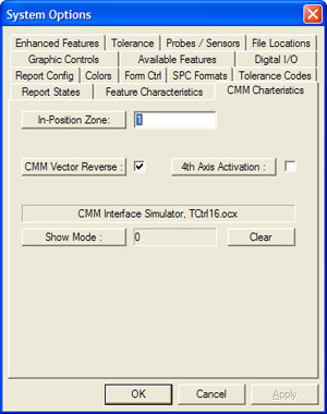
In-Position Zone
The In-Position Zone is used when the CMM must be at a
location before proceeding with the next move or operation. For example, if
the CMM has a motorized probe, the position that was used to articulate the
probe becomes a target point. During the inspection, Geomet will transition
to that point, and upon reaching it, will then articulate the probe.
The In-Position Zone provides a 3D radial distance
around the target point. Once inside that radial distance it is considered
on target. In the example of the motorized probe, it is not necessary to be
exactly on the target position, but be within a radial distance of 0.25"
will suffice. The extra time needed to transition exactly to a XYZ position
will add time, and in some cases, several seconds to the inspection time.
In-Position Zone is applied only to non-critical
positioning moves. It is designed only for non-measurement moves.
Default: 1.000"
Pressing the <In-Position Zone:> button will display a
help topic.
Data Point Dwell
The Data Point Dwell is a small time period after the
capturing of a measurement point. It disables further data points from being
accepted by Geomet. It is designed to assist manual CMM operations where the
process of capturing data points often lead to errant hits. For example,
measuring in small details where the operator will capture the data point
and have the possibility to cause an errant hit on retract.
Recommended time periods are 100 to 250. These values
are millisecond where 1000 equals 1 second.
Default: 0.0
Pressing the <Data Point Dwell:> button will display a
help topic.
CMM Vector Reverse
Geomet is designed to work with many CMMs. Not all
CMMs place the scale on the measuring machine the same way. The scale may
read left-negative to right-positive. Others can be reversed. Some CMM
models by the same manufacturer can be reversed.
This results in reverse direction sensing in the
measuring process. To test your directions, set Geomet up for Auto Direction
Sensing, activate it in your
[System Options→Enhanced
Features] page. For additional information see
Auto
Direction Sensing.
To perform the test, set Geomet up to measure a Auto
1D-Point. Slowly move the CMM in the +X direction and while moving, deflect
the probe. The point reported in the inspection report should be a +X Point.
Test all six directions and review the report to determine if they are
indeed backwards. A +X Point should not be reported as a -X Point.
If they are backwards, place (or remove) the check
next to CMM Vector Reverse.
Default: OFF
Pressing the <CMM Vector Reverse:> button will display
a help topic.
4th Axis Activation
This option activates the 4th-Axis inside Geomet. This
is commonly used on CMM that have a rotary motorized table or on Helmel's
Crank Shaft CMM. By activating the 4th-Axis, additional commands are
available such as the Wobble Coordinate System and Motion Servo commands.
It is recommended that you do not activate this option
without first checking with Helmel Technical Support to determine if the
motion controller attached to your CMM has 4th Axis capability. This is not
designed as an aftermarket option.
If you add a rotary table, such as a Haas Rotary Table
with its own Servo Control, Geomet will be able to read and control the
positioning. Under this condition, the 4th Axis option will not be
available.
CMM Interface Driver
The current CMM interface is listed here. The actual
configuration and activation has been moved off the System Option page and
now resides in GeoClean.
Show Mode
This option allows you to enter a cycle count that
Geomet will use when performing an inspection. Geomet will automatically
cycle the inspection program the number of time you request. When it counts
down to zero, the inspection program will stop.
The <Clear> button will reset the counter to zero.
This can be done even during the inspection run.
The normal use of this mode is for life endurance
tests, repeatability tests and trade shows where the CMM will cycle a
predetermined number of inspections.
NOTE: It is imperative that the ending point of
your inspection program has an unobstructed path to the start of the
program. Always ensure there is an exiting IP in your part inspection
program.
Applying your Selections
When finished making all your selections, press the
<Apply> button and close the System Options by pressing the <Ok> button.
return to System Options
|