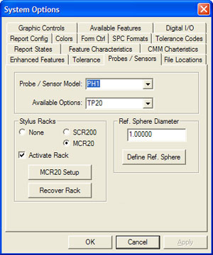
Building the hardware configurations starts with the Probe / Sensor Model
selections. Choose the appropriate probe system from this drop down list.
This list is dynamic and it changes based on the settings of your system.
For example, should you have Direct Computer Control (DCC) you will have
access to Stylus Racks.
Some choices such as manual indexing probes on DCC style systems offer
two selections. Manual indexing probes can be used on DCC systems, however
the motion during and inspection must be suspended providing an opportunity
for the operator to manually articulate the probe as needed.
To accomplish this, these probes can be selected with *No Prompt
or *Auto Prompt. The Auto Prompt option will suspend the execution of
the inspection program and display a message on the display when a probe
change is required. The operator will then release the pause and execution
will continue. The No Prompt option is used when manual probe articulation
is not required during the inspection process and suspending motion is not
required.
Stylus Racks
The Stylus Rack Group will self configure based on the selection in Probe
/ Sensor Model. For example is you have chosen the TP-ES, all choices inside
the Stylus Rack Group will be removed. Choose a PH5 and the option will
appear. Choose the appropriate Stylus Rack if one is to be used.
Activate Rack
Used to activate or disable Stylus Racks.
Recover Rack
When deselecting the Stylus Rack, the basic orientation and location are
stored, but the use Stylus Rack flag is turned off. Reactivate the Stylus
Rack normally requires a new setup. If the stored Stylus Rack information is
still current, press the <Recover Rack> button to reinstate the
stored values.
Available Options
Once the Probe Head and Stylus Rack choices have been made, the Available
Options choices will update to show all possibilities. Choose from the
selections the probe body that is installed on your CMM.
Reference Sphere Diameter
Enter the size of your nominal Reference Sphere Diameter.
 Define
Ref. Sphere Define
Ref. Sphere
This is an optional setting to define your Reference Sphere. The
Reference Sphere is defined by it's Diameter, Location, Stem Diameter and
Stem Orientation.
When the full auto calibration tool is released in December 2006, this
tool will be required to identify the limitations to the motion that Geomet
will develop to ensure safe transition during probe calibrations.
|