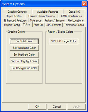
 System Options System Options
The Colors Option page defines the color used in
the display of features in the CAD Graphics region in Geomet. The Color
option page also provides access to adjust the color of the XYZ Digital
Readout of the Vector Point Display when the target position has been
reached.

Sets the default color used for displaying solid
features.
Default: Red 90, Green 90, Blue 90
Sets the default color used for displaying wire frame
features.
Default: Red 94, Green 94, Blue 94
Sets the default color used for displaying selected
features.
Default: Red 145, Green 121, Blue 47
Sets the default color used for displaying the current
feature while performing an inspection run.
Default: Red 145, Green 121, Blue 47
Sets the default color for the background of the
graphics region.
Default: Red 0, Green 0, Blue 0
Sets the default color for the
Vector Point XYZ position on the
digital readout display when at the target position.
Default: Red 0, Green 255, Blue 0
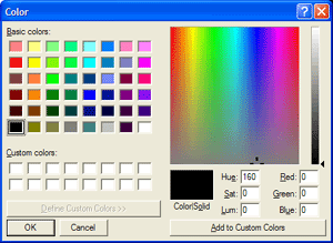
Color Dialog
Using the Color Selection Tool, choose a new color to apply to your
choice.
 |
|
Custom Color Selection Tool |
To apply your new color, press the <Ok> button.

Geomet will retain custom colors that you have selected. The Windows
Color Selector requires that you follow these steps.
1. Select a swatch location under “Custom colors”.
2. Choose or create a color.
3. Select <Add to Custom Colors>.
Applying your Selections
When finished making all your selections, press the
<Apply> button and close the System Options by pressing the <Ok> button.
return to System Options
|


