- MCS - Machine Coordinate System
- PCS - Part Coordinate System
- FCS - Fixture Coordinate System
- ICS - Interim Coordinate System
-
Clearance Coordinate Systems
The MCS is the XYZ position on the CMM with respect to the Home Position. The MCS axes
are mutually parallel with the movement of the CMM
Most manual CMMs do not have a home position, therefore the home position is the
location of the CMM at the point of starting the system. Some manual CMMs do offer a home
position that requires the operator to manually move the CMM over reference marks one axis
at a time.
On a DCC system, a start-up procedure requires that you "Home" the CMM which
drives to the designated home location and establishes a repeatable XYZ zero point.
A MCS is therefore not a valid coordinate system to obtain reliable measured values for
your part inspection.
The PCS is the foundation that establishes the Orientation, Alignment and Origin of
your part inspection. PCSs are simply the frames of reference in which part feature
locations are defined.
Traditional drawings were made using 2D projections to represent 3D objects. Each 2D
view shared a common reference point and common axis of alignment allowing the building of
3D features. In fact, a 3D dimensional PCS is implied.
Today, it is common to create machined parts using a 3D model created by many popular
CAD tools. These models may contain all necessary information for the machinist to create
the part and for the inspector to validate the final production. However, the PCS is still
implied using the same procedures as if measured from a 2D drawing.
The established method for creating and using a datum frame reference can be found in
the ASME Y14.5M - Dimensioning and Tolerancing manual. Geomet uses these accepted
practices in the application of PCS.
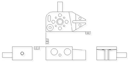
To better understand this let us consider the multi-projection part shown below:
|
 |
|
Multi-Projection 2D Drawing |
In order to measure this part on a coordinate measuring machine we shall need to
contact it with probes on all sides. In planning to do this it is helpful to visualize the
3D coordinate system of the part. Let us do this by making a perspective drawing from one
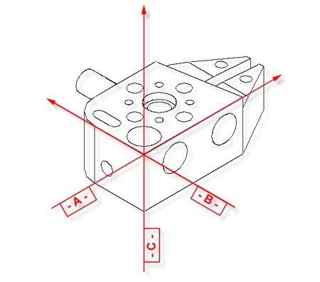
possible direction and then overlaying a 3D PCS. The figure below is one possible view if
the 3D dimensional PCS.
|
 |
|
Example : 3D Part Coordinate System |
The way in which the PCS is overlaid on the part is determined by the datums defined in
the drawing. Notice that each datum can be represented by a standard measured feature; The
-A- datum is a ZX plane, datum - B - is a YZ plane and datum - C - is a XY plane. The XY,
YZ and ZX planes are orthogonal to one another.
The important point to remember is that the two dimensional drawings we deal with are
derived from three dimensional concepts, and in order to effectively measure a 3D part
with a coordinate measuring machine we must "see" the 3D PCS with the part. This
is made easier by looking at the actual part and at the same time as we study the drawing
and making a habit of constructing imaginary planes in the part representing the datums
defined in the drawing.
PCS Base Planes are the extracted XY, YZ or ZX datum planes of an establishes Part
Coordinate System. When extracted through the Recall Component tool, they become
constructed planes and given a feature number in the inspection report. They and can be
used in all constructions and other feature tools including the application of tolerance
nominals.
Since features of machine parts are defined in terms
of their datum references, we must create Part Coordinate Systems reflecting those datums
before the features can be measured. Since coordinate measuring machines have their own
coordinate system, namely a system of mutually orthogonal axes of motion referred to as
the Machine Coordinate System (MCS), the first problem we face is to create the PCS within
the MCS. This is not trivial.
One way to create a PCS within a coordinate measuring machine is to make the PCS
coincide with the MCS. The procedure consists of physically aligning the datum surfaces of
the part parallel to the axes of motion of the machine and setting the X, Y and Z displays
to zero with an edge finder probe in contact with datum surfaces or with a taper probe
seated in a datum bore. Once the MCS and the PCS have been made to coincide, all
dimensions found on the display of the coordinate measuring machine are also feature
locations on the part.
|
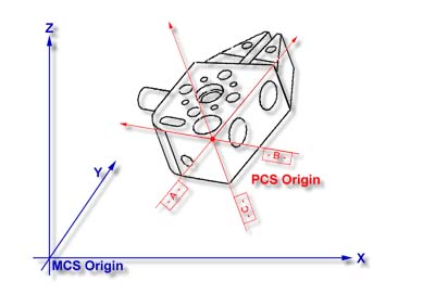 |
|
GeoWidget PCS shown in relationship to the MCS |
Making the PCS and MCS coincide physically can be extremely time consuming, and
sometimes impossible. We can eliminate the problem by using Geomet to create and store a
skewed PCS. Once a PCS has been established, the computer converts raw data collected in
the machine coordinates into measurement results in part coordinates. In the figure at the
right you will see a part coordinate system with X, Y and Z axes nested inside a machine
coordinate system with its own X, Y and Z axes.
The MCS and the PCS are totally skewed relative to each other. With the help of Geomet
any point in the MCS can be expressed in the PCS.
As Geomet can manage the link between an MCS and a totally skewed PCS we no longer need
to physically align the parts to the machine. But, we need to create the skewed PCS in
Geomet before it can manage the link. The job of creating the PCS will be simple once we
understand a few fundamental principles. A PCS nested within the MCS
A FCS is a previously measured coordinate system saved away for recall and used in part
inspection programs. The use of an FCS allows a repeatable location in the CMM measuring
cube where inspections take place. An example would be a cradle fixture that holds a
production part in one orientation and fixed location,
see FCS
Manager.
The use of an FCS requires that the CMM have a known home position which is common on
all DCC CMMs and on few manual CMMs.
The process of creating a FCS entails establishing a PCS on the fixture and then
activating the FCS Manager to append the specific geometry values associated with the
established PCS to the FCS database. Using an FCS requires recalling the FCS by the
assigned number through the Coordinate System Manager.
The ICS is a coordinate system that has not been completed to the status of a PCS. For
example, when Geomet begins a part inspection, the only coordinate system available is the
MCS. Should the part to be inspected have the orient applied to it, Geomet creates an ICS
based on the orient vector data and brings forward the alignment and origin data from the
MCS.
During the inspection process, reported results on features are hidden until the PCS is
completed. Only then will the reported data be meaningful.
A Clearance Coordinate System are used to create safe zones
around the part being inspected and around any fixtures associated with the inspection.
The Clearance CS contains 3 clearance planes, identified as XY, YZ and ZX base planes and an
origin. These clearance planes are used as safe transition planes where the CMM can
perform DCC moves without concern of accidental probe encounters.
Clearance CSs are used
with
Offline IPs and Entry / Exit IPs in auto features.
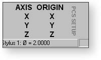
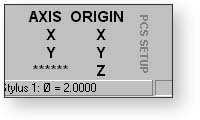
In order to ensure that a complete PCS has been established, Geomet provides a visual
PCS Setup Guide to remind you of the missing components of the current PCS under
construction. In figure 1, we show the setup guide with all axis and origins still
requiring definition.
 |
 |
| figure 1, PCS Setup Guide |
figure 2, Completed Z Axis |
When you establish one of the PCS components, such as the Z primary axis derived from
the Orient function on a measured or recalled qualifying
feature, the setup guide will reflect the completion by "signing- off" that
component with a series of "*******" as shown in figure 2. During the building
of a PCS, Geomet maintains an Interim Coordinate System, ICS, which contains the resolved
transformations and carries forward the missing components from the MCS, see
ICS.
During the inspection process, additional PCSs may be required. Should you want to
create another PCS by starting with the
Orient function, the PCS
Setup Guide will reappear and further results will be suppressed until the ICS is resolved
into a completed PCS. The setup guide will not reappear with basic transformations on a
current, completed PCS that results in a new PCS. These commands are:
It should be noted that as long as a PCS is under construction, no results are
displayed with each measured feature. When the PCS is completed, the PCS Guide Box will
disappear from view and the suppression of results is removed.
|


