 For proper operations Geomet must know the location and orientation of the
Stylus Rack. To access this operation click on the <MCR20 Setup>
or <SCR200 Setup> for the appropriate stylus rack located
in the drop down menu [Qualify→Probe System Setup Tools]. The first
step
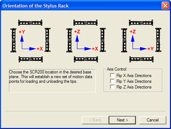
you will encounter is to identify the orientation and base plane for the
Stylus Rack.
For proper operations Geomet must know the location and orientation of the
Stylus Rack. To access this operation click on the <MCR20 Setup>
or <SCR200 Setup> for the appropriate stylus rack located
in the drop down menu [Qualify→Probe System Setup Tools]. The first
step
you will encounter is to identify the orientation and base plane for the
Stylus Rack.
Your CMM has three base planes XY, YZ and ZX. Within each base plane
you can orient your Stylus Rack to allow maximum access to the rack and your
inspection process. The location of the Stylus Rack must be completely within
the motion cube of you CMM.
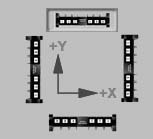 The
example at right shows the Stylus Rack located in the rear of the CMM in the XY plane. The access to the bays
is accomplished in the +Y direction. The
miniature symbols are selectable buttons, which are selected by left
clicking on the symbol with your left mouse button. Once you have
selected the proper orientation, Geomet will configure the motion path
required to access each bay.
The
example at right shows the Stylus Rack located in the rear of the CMM in the XY plane. The access to the bays
is accomplished in the +Y direction. The
miniature symbols are selectable buttons, which are selected by left
clicking on the symbol with your left mouse button. Once you have
selected the proper orientation, Geomet will configure the motion path
required to access each bay.
The twelve choices displayed are the most common positions for the
Stylus Rack. However there are certain conditions such as having a CMM with
switched X-Y axis or positioning the rack on the left YZ plane versus
the right YZ plane that will require the use of the Axis Control check
boxes. For example, if you mount the rack in the YZ plane it is assumed
you are looking at it from the +X direction and the default motion paths
will be established accordingly. But if you mount the rack where you
must access it from the –X direction you will be required to check the
Flip Z and Y Axis Directions check box.
After you have made your selections press the <Next> button to
continue the setup.
MCR20: Return to
Setup Introduction,
Proceed to Step 2.
SCR200: Return to Setup Introduction,
Proceed to Step 3.


