The Intersection command requires that the Circle and Line reside in the
same PCS and share the same PCS Base Plane. The Intersection command uses
either the last two measured or constructed features or two random
highlighted features in the inspection report.
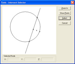
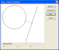
The intersection between a Circle and Line provides 1,
3 or 5 possible solutions. All solutions create a 2D Point feature in the same
PCS projection plane as the features. In figure 1, we have two features that
intersect. In figure 2, we have two features that do not intersect, but can
have valid solutions.
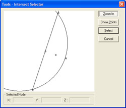
 When the node selection is obscured in the graphics
display, press the <Zoom In> button which will redraw the graphics to
encompass only the nodes for easier selection, see figure 3.
When the node selection is obscured in the graphics
display, press the <Zoom In> button which will redraw the graphics to
encompass only the nodes for easier selection, see figure 3.
|
 |
|
figure 3,
Zoom-In Option. |

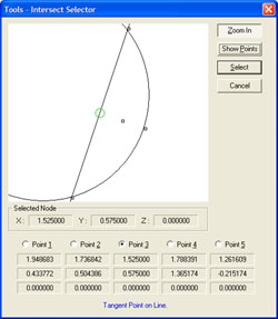
The Show Points option, expands the Intersect Tool to show all possible
solutions.
 In
the figure below, Point #3 has been selected by left-clicking on the radio
button next to Point 3.
In
the figure below, Point #3 has been selected by left-clicking on the radio
button next to Point 3.
|
 |
|
figure 4,
Show Points. |
To graphically view the reported XYZ values can be
accomplished by passing your mouse pointed over a node. When the mouse
pointer touches a node, a small information window appears as shown
below.
|
 |
|
figure 5,
Show XYZ Position. |
To select the node for reporting, left-click on the
graphic node, or if Show Points is expanded, select the Point as
described above. In the graphics, the node will change from a square to
a green circle.
|
 |
|
figure 6,
Node Selection. |
 Once
the node has been chosen, press the <Select> button to close the
Intersect Tool and report the intersect solution on the inspection
report.
Once
the node has been chosen, press the <Select> button to close the
Intersect Tool and report the intersect solution on the inspection
report.
Circle / Line - Single Point Solution
Only under one condition there can be one intersect
solution. That is where the circle and line touch only at the tangent point.
When asking for the Intersection, the system will report the one solution in
your inspection report. This point corresponds to node ID number 3 from the
table above.
However, when performing repeated inspections this
condition is rare. When Geomet determines the two features do not repeat by
touching in only the one selected point, and in fact does not intersect, the
solution will default to the mid point and miss distance.
Circle / Line - Default Reporting
When teaching a part for auto-inspection variances to
the part during manufacturing may affect the reported intersection solution.
For example, the features may intersect as shown in figure 1 during the
self-teach phase, but later during the inspection routine they fail to
intersect as shown in figure 2.
If the original solution to report was node #4 or #5
when the inspection report was created, they will report as node #3 during inspection
should the features fail to intersect.