The Intersection command requires that the Circles reside in the same PCS
and share the same PCS Base Plane. The Intersection command uses either the
last two measured or constructed features or two random highlighted features
in the inspection report.
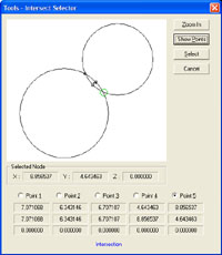
The Circle / Circle Intersection tool provides
extended capabilities as there is more than one solution. The intersection between two Circle provides 1, 3 or 5
possible solutions. All solutions are 2D Point features in the same PCS
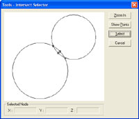
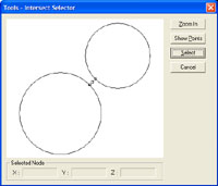
projection plane as the circles. In figure 1, we have two circles that
intersect. In figure 2, we have two circles that do not intersect, but can
have valid solutions.
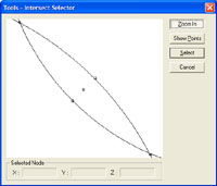
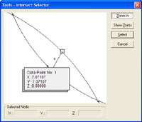
 To view all possible point solutions, press the <Show
Points> button. The display will expand to show the 3 or 5 possible
solutions, see figure 5. You can select a node in the list by placing
a bullet next to the corresponding node ID.
To view all possible point solutions, press the <Show
Points> button. The display will expand to show the 3 or 5 possible
solutions, see figure 5. You can select a node in the list by placing
a bullet next to the corresponding node ID.
Circle / Circle - Single Point Solution
Only under one condition there can be one intersect
solution. That is where the circles touch at only one point. When asking for
the Intersection, the system will report the one solution in your inspection
report. This point corresponds to node ID number 3 from the table above.
However, when performing repeated inspections this
condition is rare. When Geomet determines the two circle do not repeat by
touching in only the one selected point, and in fact does not intersect, the
solution will default to the mid point and miss distance.
Circle / Circle - Default Reporting
When teaching a part for auto-inspection variances to
the part during manufacturing may affect the reported intersection solution.
For example, the circle may intersect as shown in figure 1 during the
self-teach phase, but later during the inspection routine they fail to
intersect as shown in figure 2.
If the original solution to report was node #4 or #5
when they intersected, they will report as node #3 during inspection.