Features must share a common axis and are contained in
the current Part Coordinate System. For example a 2D XY Circle shares a
common axis of Y with a 2D line reporting the Y axis pierce value. The XY
Cylinder Axis Pierce Point shares both the X and Y with the reported
position of a 3D Sphere.
Should the distance routine determine there are no
shared axes between the two features, an error will be reported. The
Distance routine utilizes the current Reporting Format under the following
conditions.
Reporting Formats
The reported distance values are direction sensitive. For example if we
calculate the distance between several points to a plane. The distance
reported will indicate whether the points are above, or below the plane.
 To
control the direction sign of the reported value for a distance, select the
reference features in the as shown in the example here.
To
control the direction sign of the reported value for a distance, select the
reference features in the as shown in the example here.
Distance reported in feature #6 is the calculated distance between
feature #4 - #5. The result is a negative value.
To obtain a positive result, as shown in feature #9, we used feature #7 -
#8.
Cartesian: Calculates the results in X, Y,
and/or Z values
that are parallel to the current Part Coordinate System.
Polar: Calculates the results in Radius and
project angle components of 2D and 3D distance solutions. Should the
distance routine determine only a 1D solution is possible, the reporting
format will default to Cartesian.
Special considerations should be taken when using the
Distance routine. For example the distance between two -Z planes is
calculated along the Z-axis of the current Part Coordinate System. This may
not reflect the desired results when the data points used to calculate the
planes are taken a distance from the PCS Origin. Any parallel deviation
between the planes will accentuate the distance value when projecting to the
Z-axis of the PCS.
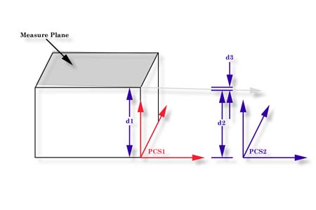
Referring to figure above, we have two established Part Coordinate Systems. PCS 1 is
established on the base of the 2.000" gage block. PCS 2 is located 4.000" inches
in the X direction from the right side of the gage block.
Two planes were measured, one representing the lower base and one on top of the gage
block, The lower base plane was used to establish the XY PCS Base Plane for both PCS 1 and
2. The top plane had a AZ/X of 89.9943° and the AY/Z was 90.0000°. The intersection with
the pierce point with the PCS1 Z Axis, d1, is reported at 1.9999".
The reported pierce point on the Z axis of PCS2, d2 is 1.9995". By
not having PCS localized to the actual measured surfaces we introduced 0.0004",
d3,
error!
The chart below illustrates the feature
characteristics used in distance reporting.


