Command Activation
| f |
Construct→Angle |
 |
| Keyboard |
Main Menu |
Toolbar |
Definition
The Angle routine determines
the angle between two selected previously measured or constructed features.
In the case of two 3D features, such as cylinders and planes, the reported
results can be three projection angles or the theta angle between features.
Applying Angle
The Angle routine uses the following feature
characteristics for reporting.
| |
2D Line |
3D Line |
Plane |
Cyl |
Cone |
|
Angle Derived From: |
Projected Line Vector in PCS |
Line Direction vector |
Plane Normal Vector |
Axis |
Axis |
To obtain the Angle result, press the < f > keystroke or
use the toolbar or drop-down menu command. When no features are highlighted
in your report, the angle of the last two measured or constructed features
will be used. To obtain the angle between two non-consecutive features,
locate and highlight those features in the Graphics area or Inspection
Report.
The angle reported will be in PCS base plane
projection values. Using the plane as an example, see figure 1, we
will illustrate the process by which angles are moved from a 3D feature and
projected into the Part Coordinate Base Planes.
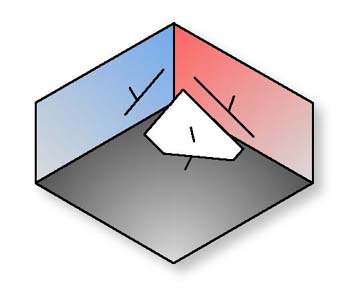 |
| figure 1, Plane represented in the
current PCS |
The direction of a plane is defined by the vector normal, pointing out of the
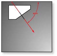
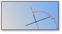
plane. Figure 1 shows a plane with its projection into each PCS base plane. The normal,
when projected into each PCS base plane provides the attitude in angles, see figures
2, 3, 4.
 |
 |
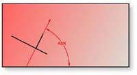 |
| figure 2, AX/Y Projection |
figure 3, AY/Z Projection |
figure 4, AZ/X Projection |
By default, the angle between two 3D features are
reported as the Theta Angle, or the angle directly between the two features
regardless of the current PCS. To switch the reporting to projection angles,
highlight the Angle feature and right-click to activate the feature
sub-menu. Choose [Projection Angles] and the reporting will switch to AX/Y,
AY/Z and AZ/X values in the current PCS.
Review of Reported Feature Angles
The direction a feature was measured will determine
the angle reported. For example; measuring a +Y 2D line in the +X direction
will result is a reported angle from +0° to +90°. Measuring the line in the
-X direction the angle would be the supplement, or -180° to -270°. The
reported feature angle will influence the angle reported between two
features. All features can be switched between its normal reported angle and
the supplement.
|


