Command Activation
| Shift + S |
Construct→Extended Distance |
|
| Keyboard |
Main Menu |
Toolbar |
Definition
The Extended Distance
routine expands the choices that can be used in determining common axis
distances between features with form. An example would be the outer
distance between two circles which results in a reported value equal to
the center-to-center distance plus the two radii.
The routine requires
that features sharing reporting axis are used. For example, two XY
Circles. The only notable exceptions are a Cylinder/Sphere and two 3D
Points. The explanation on these special relationships are provided
below.
Applying Extended Distance
The Extended Distance routine works on the follow
feature pairings:
Reporting Formats
Cartesian: Calculates the results in XYZ values
that are parallel to the current Part Coordinate System.
Polar: Calculates the results in Radius and
project angle components. The radius equals a direct line distance between
the selected nodes. The angle is the projected PCS base plane angle in the
XY, ZX or YZ base plane.
Alignments
Align in PCS: The calculated nodes are inline
with the current Part Coordinate System.
Align with Features: The calculated nodes are
inline with the direction vector passing through the center positions of the
features. This method is commonly used when combined with Polar reporting to
show the inner or outside distances of the features.
Tangent Points: The calculated nodes represent
the point of contact of a line touching both features simultaneously.
Extended Distance works with the last two features
measured or constructed , or with two previously selected features in the inspection
report.
Activating the Extended Distance Tool will show the
two features in their respective orientation, see
figure 1. Each circle will be shown with five nodes assigned
corresponding to the top, bottom, right and left extreme positions, plus a center
point node. Between the two circles will exist a node that lies on a direct
line between the circle centers and its mid point.
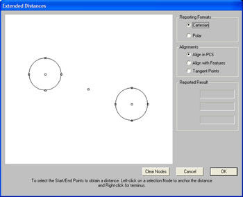 |
| figure 1,
Basic Extended Distance Tool |
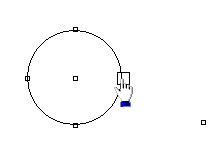
These nodes can be selected, one from each circle or
the center node to obtain the required distance. To select a node, pass your
mouse pointer over a node and the node will expand indicating you can select
it, see figure 2. Left click on the expanded
node and that becomes one of the required selected node to be used in
determining the distance.
 |
 |
| figure 2, Node selection |
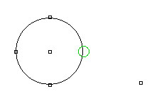
figure 3, Locking on a node |
When the node is selected, the node shape changes into
a Circle where green is the color for node one and blue is the color for
node two. Selecting node two is similar to node one except the selection
process using a right-click.
|
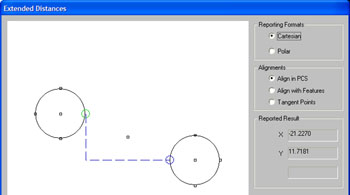 |
|
figure 4,
Selected nodes |
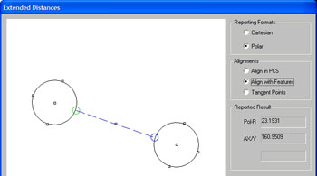
In figure 4, we show two selected nodes.
The alignment of the nodes are in line with the current PCS axis. Leader
lines are drawn to represent the distances that will be reported. We are
reporting in Cartesian coordinates with the reported values parallel to the
current PCS axis. The reported results are shown for reference.
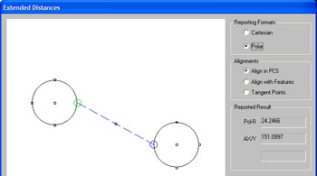
To illustrate how we get a minimum
distance, or inner distance value, we switch the Alignment choice to "Align
with Features". This will recalculate the nodes using the center-to-center
alignment, see figure 5.
|
 |
|
figure 5,
Direct
feature to feature distance. |
The Reporting Format selection was
changed to Polar to allow for direct distance between nodes. We choose our
two required nodes and the distance leader will be drawn directly between
the nodes.
If we did not switch to "Align with
Features" and attempted to retrieve the inner distance, we would get a poor
reading as shown in figure 6.
|
 |
|
figure 6,
Incorrect
Alignment Selection |
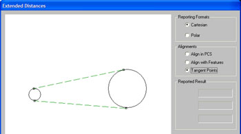
Working with tangent points can be
accomplished when selecting "Tangent Points" under the Alignment group. The
features will be redrawn to show the available nodes, see figure 7.
|
 |
|
figure 7,
Tangent
Points |
Select the two nodes as described above
to obtain the distance. Under most conditions, have your Reporting Format
set to Polar. This routine is helpful when working with oval slots and
between fillets in corners to report the straight line distance and angle.
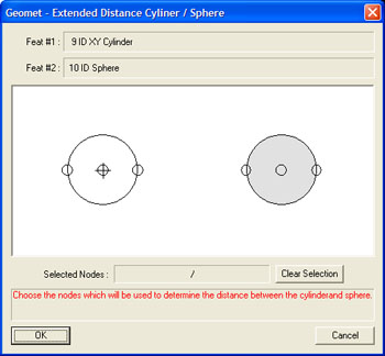
The Extended distance routine can be
applied to a Cylinder and Sphere combination. When Geomet sees that you have
selected these features, the Extended Distance tool reconfigures itself to
those pairings, see figure 8.
|
 |
|
figure 8,
Cylinder / Sphere Extended Distance |
The graphic illustration of the two
features are not shown in their respective relative position or size. This
was done to accommodate more effective use in selecting nodes. For example,
should the cylinder axis pass through the center point of the sphere, such
as a rounded end of a shaft, the nodes would overlap and it becomes
difficult to separate for clarity.
Choose the nodes using a left-click only
on each feature. When one node has been selected on each feature, a leader
line is drawn with its corresponding value, see figure 9.
|
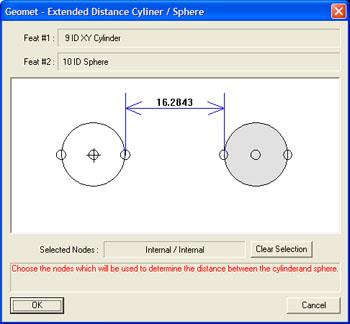 |
|
figure 9,
Inner nodes selected |
In this example, the inner nodes were
selected reporting the distance between features at the closest point of
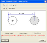
approach. In figures 10 and 11 we illustrate various selected nodes for
reporting.
 |
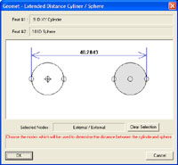 |
figure 10,
External to Center Nodes |
figure 11,
External
nodes selected |
The reported value is the direct line
distance from the selected node and is not reported as XYZ Part Coordinate
System values. The calculation of the distance is a direction
vector from the center of the sphere normal to the axis of the cylinder.
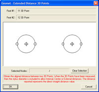
The Extended Distance routine can be
applied to a pair of 3D Points one of which must be a measured point.
Normally a 3D Point has no form or feature size. In the Extended Distance
routine, the size of a measured 3D point is the size of the stylus used when
capturing. Constructed 3D Points, when used with the Extended Distance
routine has no size. In figure 12, we illustrate two measured 3D Points
being displayed. In figure 13, we have one measured 3D Point and one
constructed 3D Point.
 |
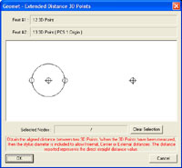 |
figure 12,
Two Measured 3D Points |
figure 13,
One Measured/One Constructed |
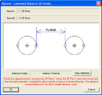
The behavior of selecting nodes is similar as
described in the Cylinder / Sphere section above. The distance reported is
calculated along a direction vector crossing through the centers of the 3D
Points.
 |
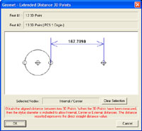 |
figure 12,
Inside Distance |
figure 13,
Inside Distance Meas. Pt / Const. Pt. |
In figure 12, the distance reported is the inner
distance between two measured 3D points. In figure 13, we illustrate the
inner distance between one measured 3D Point and a constructed 3D Point
which is derived from the intersection of two 3D Lines.
|


