To add the Reference Sphere to the graphic display of your
CMM environment provides a visual enhancement to the CMM measuring area. The
process is done by accessing the Define Reference Sphere from the drop down
menu [Qualify→Probe System Setup Tools] or through the
System Options.
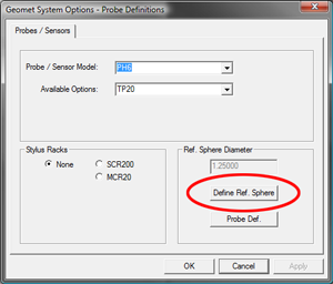
Setting up the Reference Sphere
To
build the definition of the Reference Sphere, access the setup tool through
the Geomet drop down menu, [Qualify→Probe System Setup Tools] and
press the <Define Ref. Sphere>
button.
Launch
the Reference Sphere setup tool and the access to all the Reference Sphere
parameters will appear.
Choose Standard Holder
There
are three standard Reference Sphere holders produced by Helmel. They can be
easily recognized by the reference sphere size.
Selecting one of these standard size also populates several
fields in the Parameters group. All fields except the MCS location are provided
by the Choose Standard Holder selection.
The default is the 1.0" diameter, 4.375" high holder.
Reference Sphere Basics
The origin for the Reference Sphere in the Machine Coordinate
System (MCS) is the center of the sphere. Under normal conditions, this number
is updated when you calibrate your first stylus and it will not be necessary to
change the values.
The diameter should be adjusted only when you know a accurate
size value for this reference sphere. This value is critical to the overall
accuracy of your CMM as every stylus size is determined on the accuracy of this
diameter.
Stem Direction IJK
The
Stem Direction IJK refers to the normal vector direction from the center of the
reference sphere through the stem of your reference sphere holder, see
example at right.
Under most conditions, the reference sphere is mounted
directly to the surface plate of the CMM. All Helmel standard reference sphere
and holders are this configuration and the IJK wound be:
I:
0.000
J:
0.000
K:
-1.000
Motion Configuration Values
These values refer to Approach Distance, Search Distance, Stem
Clearance and Use Stem Data. Under normal conditions, the following
recommendations are provided.
Approach Distance :
0.500 (12.7mm)
Search Distance :
0.500 (12.7mm)
Stem Clearance :
0.250 (6.35mm)
The check mark "Use Stem Data" applies these values to the
AUto-Calibration function.
NOTE: In Version 7.00.015, the motion
characteristics are not active. They have been added in preparation for the next
evolution of Auto Calibrate. Currently all motion characteristics will be
handled by the standard DCC Settings.
Height Off Table
This value is important to establish the correct positioning
on the surface plate. We suggest to obtain the correct height value, perform the
following steps.


 To
build the definition of the Reference Sphere, access the setup tool through
the Geomet drop down menu, [Qualify→Probe System Setup Tools] and
press the <Define Ref. Sphere>
button.
To
build the definition of the Reference Sphere, access the setup tool through
the Geomet drop down menu, [Qualify→Probe System Setup Tools] and
press the <Define Ref. Sphere>
button. Launch
the Reference Sphere setup tool and the access to all the Reference Sphere
parameters will appear.
Launch
the Reference Sphere setup tool and the access to all the Reference Sphere
parameters will appear. There
are three standard Reference Sphere holders produced by Helmel. They can be
easily recognized by the reference sphere size.
There
are three standard Reference Sphere holders produced by Helmel. They can be
easily recognized by the reference sphere size. The
Stem Direction IJK refers to the normal vector direction from the center of the
reference sphere through the stem of your reference sphere holder, see
example at right.
The
Stem Direction IJK refers to the normal vector direction from the center of the
reference sphere through the stem of your reference sphere holder, see
example at right.