|
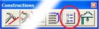
Command Activation
<~>
 |
Construct→Feature Selection |
 |
| Keyboard |
Main Menu |
Toolbar |
Introduction
Feature Selection provides expanded capabilities to Geomet through the use of random
feature selections. Geomet has been developed over the years as a sequential part
programming tool. This means that operation normally took place
on the last
'x'
number of features. For example if you wanted to obtain the distance between two coplanar
circles you would press the distance key assuming the two circles were the last two
features in your report stack. If they were not, then you would recall the circles to
ensure they were the last two features in the report.
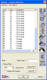 |
| figure 1, Feature Selection Tool |
Feature Selection allows you to select these features anywhere in the report and
perform the distance function. From the Feature Selection dialog, you can perform the
following:
- Distances
- Intersections
- Angles
- Bisects
- Fit Lines
- Fit Circles
- Fit Planes
- Fit Cylinder
- Fit Cylinder from Circles
- Basic Math Calculations
- Edit Tolerance Values in Groups
 |
| figure 2 |
To activate the Feature Selector anytime during your inspection process, press the
<~>, key on your keyboard, see figure 2. You can also highlight
features in your inspection report and through the
right-click submenu, choose
[Feature Selection Tool].
How the feature selection tool displays features depends on whether features were
highlight before starting the tool. If no features were highlighted, then the tool will
display all features in your report. Should you have previously highlighted some features,
then only those features will appear in the tool.
There are several filters you can use in conjunction with viewing the features. The
first filter applies to Coordinate Systems. By default, the feature selection will show
all features regardless of PCS affiliation. If you want to choose a specific PCS, use the
drop down box to choose an existing PCS. There is a button labeled <Current PCS>
which will take you directly to the current PCS of the inspection report. The selection
dialog will update to show those features in the selected PCS.
If you want to view only geometric features, place a check next to "Display only
Features". The Feature Selection tool will extract only measured and constructed
features from the inspection report.
Sorting of data is helpful to group together common features. From the Feature
Selector, you can click on the header for the column to sort. For example: click on the
"Feat" column header to sort all 1D points together, 2D points, 3D point, etc.
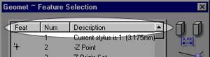 |
| figure 3, Sorting |
Use the "Num" column to reorder the features in their respective
measurement order. The "Description" column will sort common features together such
as all -Z points and all XY ID Circles. To reverse the order of sorting, click a second
time on the same header and the sort will change from ascending to descending. This can be
very helpful especially in larger programs where you can sort on the "Num" column
twice to view the last features first.
Tips
Why is all this filtering and sorting available? First, we still apply the same
constraints to feature constructions as previous versions of Geomet. For example a -Y
point can not used with a +Z point to obtain distances. Second example: a XY circle from
PCS 3 can not be used with an XY Circle from PCS 5 to construct a line.
Sorting assists the operator in grouping common features or shared Part
Coordinate Systems.
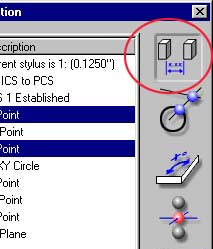 |
| figure 4, Choosing a function |
Once you have completed your feature selections choose the icons next the selector
window. In the example shown here, the distance button is being chosen. All relationship
functions, Distance, Angle, Intersect and Bisect require two features. Fit features can
have any number of features selected greater than or equal to the required feature
minimum.
Then Geomet will perform your request after validating the rules of constructions. A
new feature or result will appear in your inspection report showing the reference feature
numbers used in the calculations.
 |
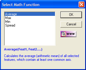
| figure 5, Math Function |
Math functions are designed to provide you with capabilities of obtaining solutions
such as the Maximum, Minimum, Spreads and Average of reported values. To access the math
capabilities, select the features to be used in the calculation and press the math
function button, see figure 5.
 |
| figure 6, Basic Math Functions |
The Select Math Function selection box will appear from which you choose the
desired function, see figure 6. When you select a function, in this example
"Average" a description of the function is shown providing you with help on your
choice.
Geomet applies certain rules to ensure that the results conform to standard practices.
Any feature can be selected, however, all features selected must be in the same Part
Coordinate System and that PCS must be the current active PCS, and share at least one
common axis. An example would be selecting the following features:
- -Z 1D Point
- YZ 2D Point
- Sphere
The result would be a 1D Point reported in the Z direction which is the lowest common
axis to all three features.
The new feature created during the calculation are common features that can be used in
other constructions such as additional relational functions (distances, bisects) or can be
used as a component in a Part Coordinate System.
The functions Average, Minimum and Maximum return a 1D, 2D or 3D Point feature. The
Spread function returns a distance similar to the Distance function. To calculate the
result, highlight the desired calculation and left-click on the <OK> button. The
Select Math Function remain displayed for additional calculations.
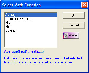 |
| figure 7, Diameter Averaging |
The Math Functions tool will review the highlighted features in the Feature Selection
Tool. Should they all be a Circle feature type, the Math Functions will include
"Diameter Averaging", see figure 7.
Diameter Averaging will take the diameters of all highlighted features and record the
following in the inspection report:
- Average Radius
- Maximum Radius
- Minimum Radius
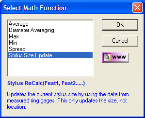 |
| figure
8,
Ring gage ReQualification |
This math tool is designed to update the size of
the current qualified stylus based on previously measure Ring Gages,
see figure 8.
Under normal operations, the ball stylus is
qualified against a known reference sphere. During this qualification
process the stylus size and location is calculated. Under most
conditions, the reference sphere qualification process is sufficient for
all general inspection requirements.
However, measure a known ring gage and the
measured diameter normally will be different than the stated ring gage
size. This happens due to variations in probe design and usage. When
qualifying against a reference sphere, the bottom of the probe will
trigger at a different pre-travel distance than a point taken at its
equator.
The Ring Gage Re-Qualification tool uses only
readings around the equator to calculate a high accuracy diameter of the
stylus. The result will only update the size of the stylus, not the
3D location. It is recommended that the Ring Gage be measured
several times as separate records. The math tool will then average all
selected Ring Gage features for a more accurate solution.
To start, set active the stylus to be updated,
see Choosing a Stylus, then follow
these steps:
- Create a Part Coordinate System on your Ring
Gage.
- Measure the Ring Gage as an ID or IR Circle.
- Activate the Feature Selection Tool.
- Highlight the Ring Gage features.
- Select the Math button, see figure 8.
- Enter the Ring Gage Radius when prompted.
- Geomet will report the change in stylus size and
update the Stylus Manager.
NOTE: This process is designed for self
teach operations only and will not create an inspection record which
becomes part of an automated inspection.
Through this drop down menu you will find access to functions relating to disable or
enable motion for selected features, see figure 9.
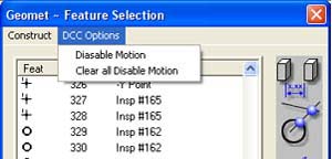 |
| figure
9, DCC Options |
DCC Options are only available to DCC style CMMs.
Through this selection process, you can set the "Disable Motion" flag for one
or more features. This instructs Geomet that when running a part inspection program to
drop into manual CMM mode for the tagged features. Geomet will resume DCC operations at
the first feature the disable flag is not set.
The [Clear all Disable Motion] command will remove all disable flags in the entire part
program. Additional information on this feature can be
found here.
NOTE: There are conditions that prevent a feature from being
successfully ran under DCC. An example would be a small diameter where the
positional tolerance is sufficiently large to interfere with the motion map.
By disabling the motion for that feature, the inspection program would drop
into manual, or joystick mode allowing the operator to measure the feature
by hand. When the feature is completed, DCC operations would resume.
Related Procedures:
Disable Motion,
ReRun Program Steps, Tutorial
|


