|
|
Technical Support Article KB10224
This topic covers the usage of the
Feature Selection Tool. Using the Feature Selection Tool is an extension
of the construction tools inside Geomet. Under normal conditions, the report
listing shown on the left side of the Geomet window shows only a few
features from which you can select and perform many operations. Often this
is not adequate and limits your access to the features not visible unless
you scroll the display.
The Feature Selection Tool displays and filters your current inspection
report displaying the features in a concise single line list which you can
sort or group by common characteristics.
Activating the Feature Selection Tool.
 Launching
the Feature Selection Tool is accomplished through the following means: Launching
the Feature Selection Tool is accomplished through the following means:
 < ~ > Keystroke. < ~ > Keystroke.
[Construct→Feature Selection] from the main menus.
When you have more than one feature selected in the inspection report
area, right-click to activate the multi-feature submenu. Select [Feature
Selection Tool] from the menu.
|
As described in the main help page,
there are several tools available to sort and filter the features listed.
The most common filter is to show only the features that are in the current
PCS. This will assist the selection process of features that will be used in
constructions such as distances and creating new features from existing
features.
Most construction tools requires that features share the same PCS.
Otherwise there is a chance for error due to projection error between
different PCSs.
Example #1 - Feature Constructions
We will use the GeoWidget for our example. The requirement is that we
measure the four 0.500" bores surrounding the 0.750" through hole.
The 4 bores are considered a 'pattern' which is tested for concentricity to
the 0.750" through bore.
 |
|
Widget Top View |
Setup the PCS on the GeoWidget using the basic
Plane - Line - Point procedure as found in
PCS Example #2.
Select
Circle
<z>, if auto-direction is not activated,
you will be prompted for the Circle type, ID OD IR OR, choose ID. Capture the four data
points on each bore starting with #1, see figure above. When you are
finished with #1, continue with four data points on each circle identified
as #2, #3, #4 and #5 respectively.
When finished, your inspection
report should have features #11 through #15 corresponding to the last 5
circles just measured.
Launch the Feature Selection
Tool, <~>.
 |
 |
 |
| Full Report |
Filtered Report |
Selected Features |
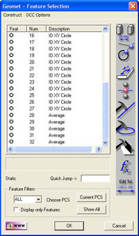
The Feature Selection Tool will
appear showing all features in your inspection report as shown above in "Full
Report". If this was a long inspection report, showing all features can
be inefficient. To filter the features shown, select the <Current PCS>
button. This will eliminate any features that do not belong to the current
PCS. To display only meaningful features, place a check next to "Display
only Features". All action features, such as PCS creation will be
eliminated leaving only usable feature, see above "Filtered Report".
In the figure, "Selected
Features", we highlighted the four 0.500" bores. To evaluate them as a
pattern, we will construct a circle through the centers by pressing the Fit
Circle button which is depressed in the "Selected Features"
illustration above.
This will result in the creation
of a circle feature. You will be prompted to report the new feature, #16, as
a Radius or Diameter. This new feature can be used for additional
constructions, as a PCS component or have tolerance values applied. In our
case, the requirement was to find out the Concentricity to the 0.750"
through bore in feature #15.
 Here
we press the < t > key, or access the function through the main menus
[Tolerances→GeoTol Form Tolerance]. Select the Concentricity option and
press <Finish> button. Here
we press the < t > key, or access the function through the main menus
[Tolerances→GeoTol Form Tolerance]. Select the Concentricity option and
press <Finish> button.
In this example, the features
were measured in a logical sequence. This is not always the case. Some
features used in constructions may have been measured in a sequence that
resulted in a large separation in the inspection report. For example, the
four bores used in our example may have been features #12, #67, #112 and
#114. The Feature Selection Tool is a logical tool that allows you to select
those features and proceed with the construction.
|
Example #2 - Math Routines
 In
this example we will use circles #1 through #4 from the example above. By
selecting those features in the Feature Selection Tool and pressing the <
fx > button, we will be presented with the Select Math Function
as show here. In
this example we will use circles #1 through #4 from the example above. By
selecting those features in the Feature Selection Tool and pressing the <
fx > button, we will be presented with the Select Math Function
as show here.
This tool will adjust the available options based on the features that
were selected. In this case, we had all circles which added the functions
"Diameter Averaging" and "Stylus Size Update". To get an understanding of
the "Stylus Size Update",
please refer here.
Using the math functions on the four circles, we can obtain the average
diameter by selecting "Diameter Averaging". The reported results include the
average diameter and the minimum and maximum diameter in the selected group.
The math selections "Average", "Max", "Min" and "Spread" return the
results of common axes. For example, if all features were 2D XY, then the
results use both the X and Y-Axis in the calculation. Should the features
not share a common reported axes, such as a 2D XY Circle and a 2D YZ Circle,
then the only common axis is the Y-Axis which will be the only reported
results.
|
Example #3 - Disable Motion
There are conditions where using the CMM under complete DCC control can
not be accomplished. For example, if there exists a 0.050" bore with a
positional tolerance of +/- 0.010" there may not be sufficient space for the
0.040" diameter probe to access the feature. Under normal conditions this is
not an issue for the DCC style CMM. However, with the large positional
tolerance, the hole can not be assured to be in the same location part to
part.
To overcome this obstacle, we would interrupt the automatic DCC
operations and drop into a manual mode only for this feature. When the
manual capturing of data points has concluded, the inspection program would
return to DCC mode to complete the inspection.
To tag a feature for manual operations use the Feature Selection Tool.
Highlight the feature i the list and from the menu in the Feature Selection
Tool, choose [DCC Options→Disable Motion]. This command will set the Disable
Motion flag on all features you have selected in the Feature Selection Tool.
This is just one method to control the Disable Flag. Another method is
through the Motion Edit Tool and can be
found here.
|
Example #4 - Adjust Tolerance Band
 The
Feature Selection Tool offers a Tolerance Tool to adjust the limits placed
on the nominal values for selected features. The
Feature Selection Tool offers a Tolerance Tool to adjust the limits placed
on the nominal values for selected features.
An example would be the need to adjust the +/- values on features that
have a tolerance applied. AT the time the inspection was created, the
required limits applied were +/-0.010". A revision to the drawing changes
those limits to +0.005 / -0.004. To change all features with one operation,
highlight those features in the Feature Selection Tool and press the
<Edit Tol> button. A limit adjustment dialog appears, see example.
Enter the new limits and accept the change using the <Ok> button. All
highlighted features will be updated.
|
| |
|
|


